
Voltage and Amperage in Solar Panel Circuits
Tags | |
UUID | b0785fad-dea1-11eb-8eb2-bc764e203090 |
Combinations of Voltage and Amperage
We saw in the equation in the previous collection that power is the product of voltage and amperage. But there are two ways to combine the power coming from multiple solar panels and we illustrate it here. We use two of the example high efficiency solar panels discussed in previous Collection pages. Typically a solar power system will contain a number of solar panels interconnected but we will illustrate the two ways to combine voltage and amperage with an example using only two solar panels.
Remember, our solar panel is a self-contained component with a positive and a negative output connection. We don't have to deal with anything internal to the solar panel. We are only concerned with how the positive and negative connections on one solar panel connect to the positive and negative connectors on other solar panels.
The example high efficiency solar panel has specifications:
- nominal max power = 325 Watts
- max power voltage = 57.6 Volts
- max power current = 5.65 Amps
If we were to combine two of these high efficiency solar panels, we could nominally generate combinations from the combined two solar panels as illustrated in the following figure:
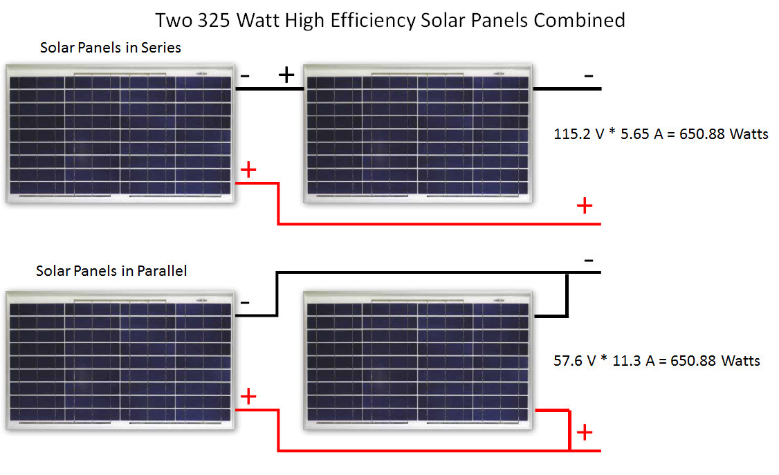
So, depending on how we wire the solar panels, we can get either a current of 11.3 Amps or 5.65 Amps from the combination of two of the example high efficiency solar panels. We can also produce our choice of 57.6 Volts or 115.2 Volts. The choice of voltage and amperage directly output from the two solar panels is a matter of how you wire the two together.
To increase current (amperage) we wire sets of solar panels in parallel with plus to plus and minus to minus. To increase total output voltage, we wire sets of solar panels in series. Series circuits connect minus to plus. In either case, the formula of equation 1 (EQ1), shows the total output power is the same whether the example solar panels are wired in parallel or series.
Notice that on the far right of the picture above labelled Two 325 Watt High Efficiency Solar Panels Combined, the circuit has a positive and negative lead extending from the right side of the picture. There would be power between these two leads and they should not touch each other in the real-world implementation. If the red positive and black negative connectors come in contact, that completes the circuit and in the simple example shown that would "short-circuit" the power and possibly damage the solar panels. We discuss ways to avoid damaging the solar power system's components and to avoid dangers of the electrical system as a whole in the vCalc Collection: Solar Panel Safety.
If the design goal of a system is to increase the voltage of the inverter, the batteries on the DC side of the inverter can be connected in series; in other words connected positive to negative between the batteries.
To increase the run-time capacity of the system, the batteries would be connected in parallel, that is positive to positive and negative to negative.
For solar inverters the concept of a micro-inverter exists where an inverter is connected to each solar panel, instead of connecting an inverter to an array of solar panels. Micro inverters may be a greater cost factor but can increase the overall efficiency of the system.
Calculators and Collections
- Comments
- Attachments
- Stats
No comments |