32.9 Summary by Benjamin Crowell, Light and Matter licensed under the Creative Commons Attribution-ShareAlike license.
Summary
Vocabulary
diffraction — the behavior of a wave when it encounters an obstacle or a nonuniformity in its medium; in general, diffraction causes a wave to bend around obstacles and make patterns of strong and weak waves radiating out beyond the obstacle.
coherent — a light wave whose parts are all in phase with each other
Other Notation
wavelets — the ripples in Huygens' principle
Summary
Wave optics is a more general theory of light than ray optics. When light interacts with material objects that are much larger then one wavelength of the light, the ray model of light is approximately correct, but in other cases the wave model is required.
Huygens' principle states that, given a wavefront at one moment in time, the future behavior of the wave can be found by breaking the wavefront up into a large number of small, side-by-side wave peaks, each of which then creates a pattern of circular or spherical ripples. As these sets of ripples add together, the wave evolves and moves through space. Since Huygens' principle is a purely geometrical construction, diffraction effects obey a simple scaling rule: the behavior is unchanged if the wavelength and the dimensions of the diffracting objects are both scaled up or down by the same factor. If we wish to predict the angles at which various features of the diffraction pattern radiate out, scaling requires that these angles depend only on the unitless ratio `lambda"/"d`, where `d` is the size of some feature of the diffracting object.
Double-slit diffraction is easily analyzed using Huygens' principle if the slits are narrower than one wavelength. We need only construct two sets of ripples, one spreading out from each slit. The angles of the maxima (brightest points in the bright fringes) and minima (darkest points in the dark fringes) are given by the equation
`lambda/d=(sintheta)/m`,
where `d` is the center-to-center spacing of the slits, and `m` is an integer at a maximum or an integer plus `1`/`2` at a minimum.
If some feature of a diffracting object is repeated, the diffraction fringes remain in the same places, but become narrower with each repetition. By repeating a double-slit pattern hundreds or thousands of times, we obtain a diffraction grating.
A single slit can produce diffraction fringes if it is larger than one wavelength. Many practical instances of diffraction can be interpreted as single-slit diffraction, e.g., diffraction in telescopes. The main thing to realize about single-slit diffraction is that it exhibits the same kind of relationship between `lambda`, `d`, and angles of fringes as in any other type of diffraction.
Homework Problems
Key
`sqrt` A computerized answer check is available online.
`int` A problem that requires calculus.
`***` A difficult problem
1. Why would blue or violet light be the best for microscopy?
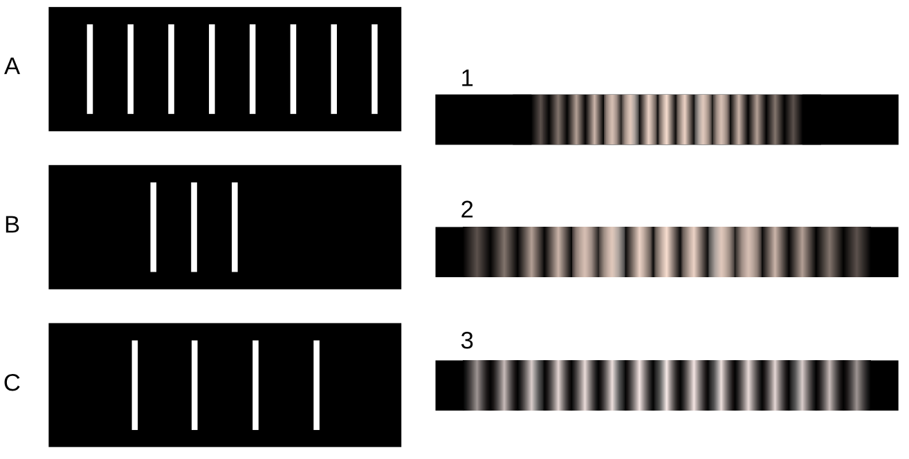
2. Match gratings A-C with the diffraction patterns 1-3 that they produce. Explain.

3. The beam of a laser passes through a diffraction grating, fans out, and illuminates a wall that is perpendicular to the original beam, lying at a distance of `2.0` m from the grating. The beam is produced by a helium-neon laser, and has a wavelength of `694.3` nm. The grating has `2000` lines per centimeter. (a) What is the distance on the wall between the central maximum and the maxima immediately to its right and left? (b) How much does your answer change when you use the small-angle approximations `thetaapproxsinthetaapproxtanapproxtheta`? `sqrt`
4. When white light passes through a diffraction grating, what is the smallest value of `m` for which the visible spectrum of order `m` overlaps the next one, of order `m+1`? (The visible spectrum runs from about `400` nm to about `700` nm.)
5. Ultrasound, i.e., sound waves with frequencies too high to be audible, can be used for imaging fetuses in the womb or for breaking up kidney stones so that they can be eliminated by the body. Consider the latter application. Lenses can be built to focus sound waves, but because the wavelength of the sound is not all that small compared to the diameter of the lens, the sound will not be concentrated exactly at the geometrical focal point. Instead, a diffraction pattern will be created with an intense central spot surrounded by fainter rings. About `85%` of the power is concentrated within the central spot. The angle of the first minimum (surrounding the central spot) is given by `sintheta=lambda"/"b`, where `b` is the diameter of the lens. This is similar to the corresponding equation for a single slit, but with a factor of `1.22` in front which arises from the circular shape of the aperture. Let the distance from the lens to the patient's kidney stone be `L=20` cm. You will want `f>20` kHz, so that the sound is inaudible. Find values of `b` and `f` that would result in a usable design, where the central spot is small enough to lie within a kidney stone 1 cm in diameter.
6. For star images such as the ones in figure diffraction spot due to diffraction at the mouth of the telescope. Assume a telescope with a diameter of `10` meters (the largest currently in existence), and light with a wavelength in the middle of the visible range. Compare with the actual angular size of a star of diameter `10^9` m seen from a distance of `10^17` m. What does this tell you?
7. Under what circumstances could one get a mathematically undefined result by solving the double-slit diffraction equation for `theta`? Give a physical interpretation of what would actually be observed.
8. When ultrasound is used for medical imaging, the frequency may be as high as `5-20` MHz. Another medical application of ultrasound is for therapeutic heating of tissues inside the body; here, the frequency is typically `1-3` MHz. What fundamental physical reasons could you suggest for the use of higher frequencies for imaging?
9. The figure below shows two diffraction patterns, both made with the same wavelength of red light. (a) What type of slits made the patterns? Is it a single slit, double slits, or something else? Explain. (b) Compare the dimensions of the slits used to make the top and bottom pattern. Give a numerical ratio, and state which way the ratio is, i.e., which slit pattern was the larger one. Explain.

10. The figure below shows two diffraction patterns. The top one was made with yellow light, and the bottom one with red. Could the slits used to make the two patterns have been the same?

11. The figure below shows three diffraction patterns. All were made under identical conditions, except that a different set of double slits was used for each one. The slits used to make the top pattern had a center-to-center separation `d=0.50` mm, and each slit was `w=0.04` mm wide. (a) Determine `d` and `w` for the slits used to make the pattern in the middle. (b) Do the same for the slits used to make the bottom pattern.

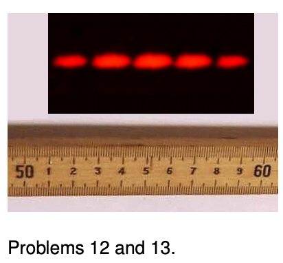
 12. The figure shows a diffraction pattern made by a double slit, along with an image of a meter stick to show the scale. The slits were `146` cm away from the screen on which the diffraction pattern was projected. The spacing of the slits was `0.050` mm. What was the wavelength of the light? `sqrt`
13. The figure shows a diffraction pattern made by a double slit, along with an image of a meter stick to show the scale. Sketch the diffraction pattern from the figure on your paper. Now consider the four variables in the equation `lambda"/"d=sintheta"/"m`. Which of these are the same for all five fringes, and which are different for each fringe? Which variable would you naturally use in order to label which fringe was which? Label the fringes on your sketch using the values of that variable.
14. Figure s on p. 878 shows the anatomy of a jumping spider's principal eye. The smallest feature the spider can distinguish is limited by the size of the receptor cells in its retina. (a) By making measurements on the diagram, estimate this limiting angular size in units of minutes of arc (`60` minutes = `1` degree).(answer check available at lightandmatter.com) (b) Show that this is greater than, but roughly in the same ballpark as, the limit imposed by diffraction for visible light. `sqrt`
Evolution is a scientific theory that makes testable predictions, and if observations contradict its predictions, the theory can be disproved. It would be maladaptive for the spider to have retinal receptor cells with sizes much less than the limit imposed by diffraction, since it would increase complexity without giving any improvement in visual acuity. The results of this problem confirm that, as predicted by Darwinian evolution, this is not the case. Work by M.F. Land in 1969 shows that in this spider's eye, aberration is a somewhat bigger effect than diffraction, so that the size of the receptors is very nearly at an evolutionary optimum.
Excercise 32A: Double-source interference
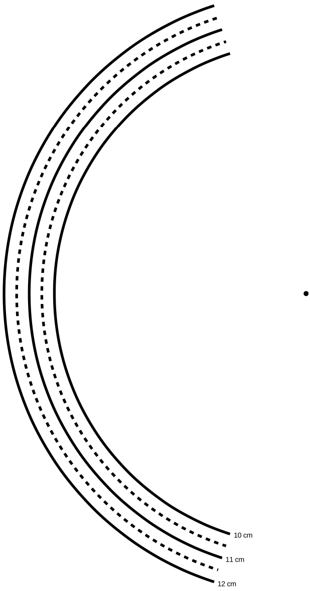
1. Two sources separated by a distance `d=2 cm` make circular ripples with a wavelength of `lambda=1` cm. On a piece of paper, make a life-size drawing of the two sources in the default setup, and locate the following points:
A. The point that is `10` wavelengths from source #1 and `10` wavelengths from source #2.
B. The point that is `10.5` wavelengths from #1 and `10.5` from #2.
C. The point that is `11` wavelengths from #1 and `11` from #2.
D. The point that is `10` wavelengths from #1 and `10.5` from #2.
E. The point that is `11` wavelengths from #1 and `11.5` from #2.
F. The point that is `10` wavelengths from #1 and `11` from #2.
G. The point that is `11` wavelengths from #1 and `12` from #2.
You can do this either using a compass or by putting the next page under your paper and tracing. It is not necessary to trace all the arcs completely, and doing so is unnecessarily time-consuming; you can fairly easily estimate where these points would lie, and just trace arcs long enough to find the relevant intersections.
What do these points correspond to in the real wave pattern?
2. Make a fresh copy of your drawing, showing only point F and the two sources, which form a long, skinny triangle. Now suppose you were to change the setup by doubling `d`, while leaving `lambda` the same. It's easiest to understand what's happening on the drawing if you move both sources outward, keeping the center fixed. Based on your drawing, what will happen to the position of point F when you double `d`? Measure its angle with a protractor.
3. What would happen if you doubled both `lambda` and `d` compared to the standard setup?
4. Combining the ideas from parts 2 and 3, what do you think would happen to your angles if, starting from the standard setup, you doubled `lambda` while leaving `d` the same?
5. Suppose `lambda` was a millionth of a centimeter, while `d` was still as in the standard setup. What would happen to the angles? What does this tell you about observing diffraction of light?

Exercise 32B: Single-slit diffraction
Equipment:
- rulers
- computer with web browser
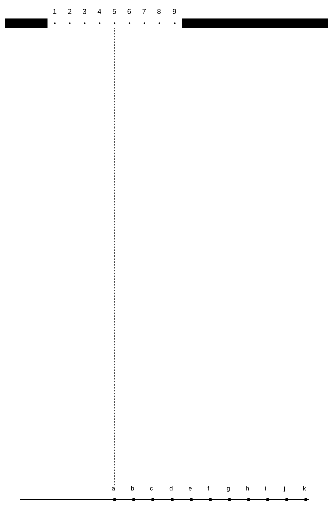
The following page is a diagram of a single slit and a screen onto which its diffraction pattern is projected. The class will make a numerical prediction of the intensity of the pattern at the different points on the screen. Each group will be responsible for calculating the intensity at one of the points. (Either 11 groups or six will work nicely -- in the latter case, only points a, c, e, g, i, and k are used.) The idea is to break up the wavefront in the mouth of the slit into nine parts, each of which is assumed to radiate semicircular ripples as in Huygens' principle. The wavelength of the wave is 1 cm, and we assume for simplicity that each set of ripples has an amplitude of 1 unit when it reaches the screen.
1.For simplicity, let's imagine that we were only to use two sets of ripples rather than nine. You could measure the distance from each of the two points inside the slit to your point on the screen. Suppose the distances were both `25.0` cm. What would be the amplitude of the superimposed waves at this point on the screen?
Suppose one distance was `24.0` cm and the other was `25.0` cm. What would happen?
What if one was `24.0` cm and the other was `26.0` cm?
What if one was `24.5` cm and the other was `25.0` cm?
In general, what combinations of distances will lead to completely destructive and completely constructive interference?
Can you estimate the answer in the case where the distances are `24.7` and `25.0` cm?
2. Although it is possible to calculate mathematically the amplitude of the sine wave that results from superimposing two sine waves with an arbitrary phase difference between them, the algebra is rather laborious, and it become even more tedious when we have more than two waves to superimpose. Instead, one can simply use a computer spreadsheet or some other computer program to add up the sine waves numerically at a series of points covering one complete cycle. This is what we will actually do. You just need to enter the relevant data into the computer, then examine the results and pick off the amplitude from the resulting list of numbers. You can run the software through a web interface at http://lightandmatter.com/cgi-bin/diffraction1.cgi.
3. Measure all nine distances to your group's point on the screen, and write them on the board - that way everyone can see everyone else's data, and the class can try to make sense of why the results came out the way they did. Determine the amplitude of the combined wave, and write it on the board as well.
The class will discuss why the results came out the way they did.

Exercise 32C: Diffraction of light
Equipment:
- slit patterns, lasers, straight-filament bulbs
station 1
You have a mask with a bunch of different double slits cut out of it. The values of w and d are as follows:
| pattern A | w=`0.04` mm | d=`.250` mm |
| pattern B | w=`0.04` mm | d=`.500` mm |
| pattern C | w=`0.08` mm | d=`.250` mm |
| pattern D | w=`0.08` mm | d=`.500` mm |
Predict how the patterns will look different, and test your prediction. The easiest way to get the laser to point at different sets of slits is to stick folded up pieces of paper in one side or the other of the holders.
station 2
This is just like station 1, but with single slits:
| pattern A | w=`0.02` mm |
| pattern B | w=`0.04` mm |
| pattern C | w=`0.08` mm |
| pattern D | w=`0.16` mm |
Predict what will happen, and test your predictions. If you have time, check the actual numerical ratios of the w values against the ratios of the sizes of the diffraction patterns
station 3
This is like station 1, but the only difference among the sets of slits is how many slits there are:
| pattern A | double slit |
| pattern B | `3` slits |
| pattern C | `4` slits |
| pattern D | `5` slits |
station 4
Hold the diffraction grating up to your eye, and look through it at the straight-filament light bulb. If you orient the grating correctly, you should be able to see the `m=1` and `m=-1` diffraction patterns off the left and right. If you have it oriented the wrong way, they'll be above and below the bulb instead, which is inconvenient because the bulb's filament is vertical. Where is the `m=0` fringe? Can you see `m=2`, etc.?
Station 5 has the same equipment as station 4. If you're assigned to station 5 first, you should actually do activity 4 first, because it's easier.
station 5
Use the transformer to increase and decrease the voltage across the bulb. This allows you to control the filament's temperature. Sketch graphs of intensity as a function of wavelength for various temperatures. The inability of the wave model of light to explain the mathematical shapes of these curves was historically one of the reasons for creating a new model, in which light is both a particle and a wave.
32.9 Summary by Benjamin Crowell, Light and Matter licensed under the Creative Commons Attribution-ShareAlike license.