LM 25.1 Capacitance and inductance Collection
Tags | |
UUID | 1ebb5aa3-f145-11e9-8682-bc764e2038f2 |
25.1 Capacitance and inductance by Benjamin Crowell, Light and Matter licensed under the Creative Commons Attribution-ShareAlike license.
25.1 Capacitance and inductance
In a mechanical oscillation, energy is exchanged repetitively between potential and kinetic forms, and may also be siphoned off in the form of heat dissipated by friction. In an electrical circuit, resistors are the circuit elements that dissipate heat.
What are the electrical analogs of storing and releasing the potential and kinetic energy of a vibrating object? When you think of energy storage in an electrical circuit, you are likely to imagine a battery, but even rechargeable batteries can only go through 10 or 100 cycles before they wear out. In addition, batteries are not able to exchange energy on a short enough time scale for most applications. The circuit in a musical synthesizer may be called upon to oscillate thousands of times a second, and your microwave oven operates at gigahertz frequencies. Instead of batteries, we generally use capacitors and inductors to store energy in oscillating circuits. Capacitors, which you've already encountered, store energy in electric fields. An inductor does the same with magnetic fields.
Capacitors
A capacitor's energy exists in its surrounding electric fields. It is proportional to the square of the field strength, which is proportional to the charges on the plates. If we assume the plates carry charges that are the same in magnitude, +q  and -q, then the energy stored in the capacitor must be proportional to . For historical reasons, we write the constant of proportionality as ,
The constant is a geometrical property of the capacitor, called its capacitance.
Based on this definition, the units of capacitance must be coulombs squared per joule, and this combination is more conveniently abbreviated as the farad, . “Condenser” is a less formal term for a capacitor. Note that the labels printed on capacitors often use MF to mean , even though MF should really be the symbol for megafarads, not microfarads. Confusion doesn't result from this nonstandard notation, since picofarad and microfarad values are the most common, and it wasn't until the 1990's that even millifarad and farad values became available in practical physical sizes. Figure a shows the symbol used in schematics to represent a capacitor.
Inductors
Any current will create a magnetic field, so in fact every current-carrying wire in a circuit acts as an inductor! However, this type of “stray” inductance is typically negligible, just as we can usually ignore the stray resistance of our wires and only take into account the actual resistors. To store any appreciable amount of magnetic energy, one usually uses a coil of wire designed specifically to be an inductor.
Unlike capacitors and resistors, practical inductors are easy to make by hand. One can for instance spool some wire around a short wooden dowel, put the spool inside a plastic aspirin bottle with the leads hanging out, and fill the bottle with epoxy to make the whole thing rugged. An inductor like this, in the form cylindrical coil of wire, is called a solenoid, c, and a stylized solenoid, d, is the symbol used to represent an inductor in a circuit regardless of its actual geometry.
How much energy does an inductor store? The energy density is proportional to the square of the magnetic field strength, which is in turn proportional to the current flowing through the coiled wire, so the energy stored in the inductor must be proportional to . We write for the constant of proportionality, giving
As in the definition of capacitance, we have a factor of 1/2, which is purely a matter of definition. The quantity is called the inductance of the inductor, and we see that its units must be joules per ampere squared. This clumsy combination of units is more commonly abbreviated as the henry, 1 henry = 1 . Rather than memorizing this definition, it makes more sense to derive it when needed from the definition of inductance. Many people know inductors simply as “coils,” or “chokes,” and will not understand you if you refer to an “inductor,” but they will still refer to as the “inductance,” not the “coilance” or “chokeance!”
Example 1: Identical inductances in series
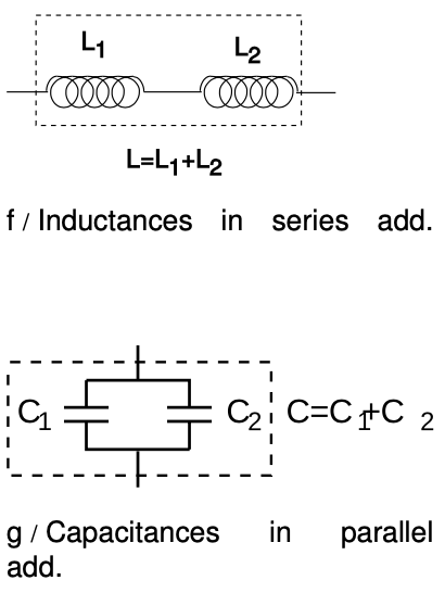
 If two inductors are placed in series, any current that passes through the combined double inductor must pass through both its parts. Thus by the definition of inductance, the inductance is doubled as well. In general, inductances in series add, just like resistances. The same kind of reasoning also shows that the inductance of a solenoid is approximately proportional to its length, assuming the number of turns per unit length is kept constant.
Example 2: Identical capacitances in parallel
When two identical capacitances are placed in parallel, any charge deposited at the terminals of the combined double capacitor will divide itself evenly between the two parts. The electric fields surrounding each capacitor will be half the intensity, and therefore store one quarter the energy. Two capacitors, each storing one quarter the energy, give half the total energy storage. Since capacitance is inversely related to energy storage, this implies that identical capacitances in parallel give double the capacitance. In general, capacitances in parallel add. This is unlike the behavior of inductors and resistors, for which series configurations give addition.
 This is consistent with the fact that the capacitance of a single parallel-plate capacitor proportional to the area of the plates. If we have two parallel-plate capacitors, and we combine them in parallel and bring them very close together side by side, we have produced a single capacitor with plates of double the area, and it has approximately double the capacitance.
Inductances in parallel and capacitances in series are explored in homework problems 4 and 6.
Example 3: A variable capacitor
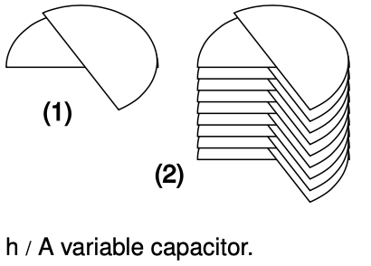
Figure h/1 shows the construction of a variable capacitor out of two parallel semicircles of metal. One plate is fixed, while the other can be rotated about their common axis with a knob. The opposite charges on the two plates are attracted to one another, and therefore tend to gather in the overlapping area. This overlapping area, then, is the only area that effectively contributes to the capacitance, and turning the knob changes the capacitance. The simple design can only provide very small capacitance values, so in practice one usually uses a bank of capacitors, wired in parallel, with all the moving parts on the same shaft.
Discussion Questions
 A Suppose that two parallel-plate capacitors are wired in parallel, and are placed very close together, side by side, so that their fields overlap. Will the resulting capacitance be too small, or too big? Could you twist the circuit into a different shape and make the effect be the other way around, or make the effect vanish? How about the case of two inductors in series?
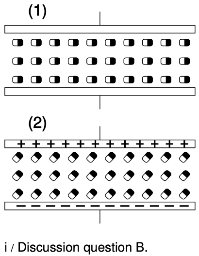
B Most practical capacitors do not have an air gap or vacuum gap between the plates; instead, they have an insulating substance called a dielectric. We can think of the molecules in this substance as dipoles that are free to rotate (at least a little), but that are not free to move around, since it is a solid. The figure shows a highly stylized and unrealistic way of visualizing this. We imagine that all the dipoles are initially turned sideways, (1), and that as the capacitor is charged, they all respond by turning through a certain angle, (2). (In reality, the scene might be much more random, and the alignment effect much weaker.)
For simplicity, imagine inserting just one electric dipole into the vacuum gap. For a given amount of charge on the plates, how does this affect the amount of energy stored in the electric field? How does this affect the capacitance?
Now redo the analysis in terms of the mechanical work needed in order to charge up the plates.
25.1 Capacitance and inductance by Benjamin Crowell, Light and Matter licensed under the Creative Commons Attribution-ShareAlike license.
Calculators and Collections
Equations
- Energy of a Capacitor vCollections Use Equation
- Energy stored in an inductor vCollections Use Equation
- Comments
- Attachments
- Stats
No comments |
