32.5 Double-slit diffraction by Benjamin Crowell, Light and Matter licensed under the Creative Commons Attribution-ShareAlike license.
32.5 Double-slit diffraction
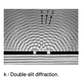
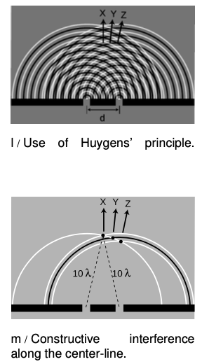
 Let's now analyze double-slit diffraction, k, using Huygens' principle. The most interesting question is how to compute the angles such as X and Z where the wave intensity is at a maximum, and the in-between angles like Y where it is minimized. Let's measure all our angles with respect to the vertical center line of the figure, which was the original direction of propagation of the wave.
 If we assume that the width of the slits is small (on the order of the wavelength of the wave or less), then we can imagine only a single set of Huygens ripples spreading out from each one, l. White lines represent peaks, black ones troughs. The only dimension of the diffracting slits that has any effect on the geometric pattern of the overlapping ripples is then the center-to-center distance, d, between the slits.
We know from our discussion of the scaling of diffraction that there must be some equation that relates an angle like Δ to the ratio lambda"/"d,
lambda/dharrtheta_Z.
If the equation for theta_Z depended on some other expression such as lambda+d or lambda^2"/"d, then it would change when we scaled lambda and d by the same factor, which would violate what we know about the scaling of diffraction.
Along the central maximum line, X, we always have positive waves coinciding with positive ones and negative waves coinciding with negative ones. (I have arbitrarily chosen to take a snapshot of the pattern at a moment when the waves emerging from the slit are experiencing a positive peak.) The superposition of the two sets of ripples therefore results in a doubling of the wave amplitude along this line. There is constructive interference. This is easy to explain, because by symmetry, each wave has had to travel an equal number of wavelengths to get from its slit to the center line, m: Because both sets of ripples have ten wavelengths to cover in order to reach the point along direction X, they will be in step when they get there.
 At the point along direction Y shown in the same figure, one wave has traveled ten wavelengths, and is therefore at a positive extreme, but the other has traveled only nine and a half wavelengths, so it at a negative extreme. There is perfect cancellation, so points along this line experience no wave motion.
But the distance traveled does not have to be equal in order to get constructive interference. At the point along direction Z, one wave has gone nine wavelengths and the other ten. They are both at a positive extreme.
self-check:
At a point half a wavelength below the point marked along direction X, carry out a similar analysis.
(answer in the back of the PDF version of the book)
To summarize, we will have perfect constructive interference at any point where the distance to one slit differs from the distance to the other slit by an integer number of wavelengths. Perfect destructive interference will occur when the number of wavelengths of path length difference equals an integer plus a half.
Now we are ready to find the equation that predicts the angles of the maxima and minima. The waves travel different distances to get to the same point in space, n. We need to find whether the waves are in phase (in step) or out of phase at this point in order to predict whether there will be constructive interference, destructive interference, or something in between.
One of our basic assumptions in this chapter is that we will only be dealing with the diffracted wave in regions very far away from the object that diffracts it, so the triangle is long and skinny. Most real-world examples with diffraction of light, in fact, would have triangles with even skinner proportions than this one. The two long sides are therefore very nearly parallel, and we are justified in drawing the right triangle shown in figure o, labeling one leg of the right triangle as the difference in path length, L-L', and labeling the acute angle as theta. (In reality this angle is a tiny bit greater than the one labeled theta in figure n.)
The difference in path length is related to d and theta by the equation
(L-L')/d=sintheta.
Constructive interference will result in a maximum at angles for which L-L' is an integer number of wavelengths,
L-L' = mlambda [condition for a maximum; m is an integer]
 Here m equals 0 for the central maximum, -1 for the first maximum to its left, +2 for the second maximum on the right, etc. Putting all the ingredients together, we find (mlambda)"/"d=sintheta, or
(lambda)/d = (sintheta)/m [condition for a maximum; m is an integer]
Similarly, the condition for a minimum is
(lambda)/d = (sintheta)/m [condition for a maximum; m is an integer plus 1/2]
That is, the minima are about halfway between the maxima.
As expected based on scaling, this equation relates angles to the unitless ratio lambda"/"d. Alternatively, we could say that we have proven the scaling property in the special case of double-slit diffraction. It was inevitable that the result would have these scaling properties, since the whole proof was geometric, and would have been equally valid when enlarged or reduced on a photocopying machine!
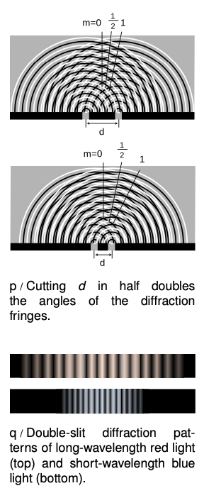
Counterintuitively, this means that a diffracting object with smaller dimensions produces a bigger diffraction pattern, p.
Example 1: Double-slit diffraction of blue and red light
Blue light has a shorter wavelength than red. For a given double-slit spacing d, the smaller value of lambda"/"d for leads to smaller values of sintheta, and therefore to a more closely spaced set of diffraction fringes, (g)
Example 2: The correspondence principle
Let's also consider how the equations for double-slit diffraction relate to the correspondence principle. When the ratio lambda"/"d is very small, we should recover the case of simple ray optics. Now if lambda"/"d is small, sintheta must be small as well, and the spacing between the diffraction fringes will be small as well. Although we have not proven it, the central fringe is always the brightest, and the fringes get dimmer and dimmer as we go farther from it. For small values oflambda"/"d, the part of the diffraction pattern that is bright enough to be detectable covers only a small range of angles. This is exactly what we would expect from ray optics: the rays passing through the two slits would remain parallel, and would continue moving in the theta=0 direction. (In fact there would be images of the two separate slits on the screen, but our analysis was all in terms of angles, so we should not expect it to address the issue of whether there is structure within a set of rays that are all traveling in the theta=0 direction.)
Example 3: Spacing of the fringes at small angles
 At small angles, we can use the approximation sinthetaapproxtheta, which is valid if theta is measured in radians. The equation for double-slit diffraction becomes simply
lambda/d=theta/m,
which can be solved for theta to give
theta=(mlambda)/d.
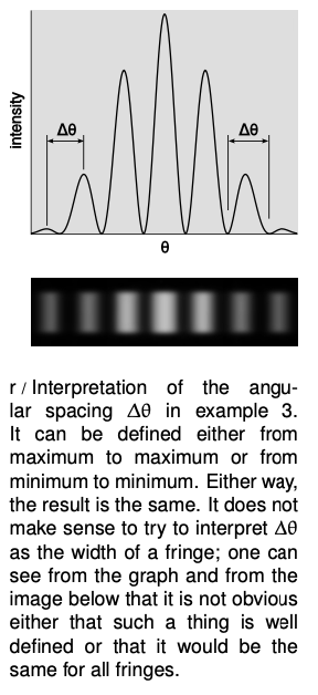
The difference in angle between successive fringes is the change in theta that results from changing m by plus or minus one,
Deltatheta=lambda/d.
For example, if we write theta_7 for the angle of the seventh bright fringe on one side of the central maximum and theta_8 for the neighboring one, we have
theta_8-theta_7=(8lambda)/d-(7lambda)/d
=lambda/d,
and similarly for any other neighboring pair of fringes.
Although the equation lambda"/"d=sintheta"/"m is only valid for a double slit, it is can still be a guide to our thinking even if we are observing diffraction of light by a virus or a flea's leg: it is always true that
(1) large values of lambda"/"d lead to a broad diffraction pattern, and
(2) diffraction patterns are repetitive.
In many cases the equation looks just like lambda"/"d=sintheta"/"m but with an extra numerical factor thrown in, and with d interpreted as some other dimension of the object, e.g., the diameter of a piece of wire.
32.5 Double-slit diffraction by Benjamin Crowell, Light and Matter licensed under the Creative Commons Attribution-ShareAlike license.