Transformer Window Utilization Factor Ku
Tags | |
UUID | 555aa366-9a6b-11e6-9770-bc764e2038f2 |
This Transformer Window Utilization Factor (Ku) equation computes the ratio of the total amount of copper that appears in the window of a transformer to the total area of the transformer window. This equation for Ku basically measures the amount of available space in the window that contains or "utilizes" copper. It estimates the amount of space in the window that is used by insulation and buy air between the wire windings and it does not include this space in the calculation of Ku.
This Transformer Window Utilization Factor is just one of many contributing factors in the design of a functional, effective and efficient transformer.
Inputs
- Wire Gauge -- chosen from a set of standard AWG wire gauges
- Insulation thickness -- chosen from a set of standard designations for the thickness of insulation on a wire
- S3 - the effective window which estimates the portion of the transformer window which contains windings (see explanation below)
- S4 - the "insulation factor" which gauges the amount of the transformer window filled by insulation (see explanation below)
The Computation
Ku is a normalized window utilization, meaning the ratio of the amount of space in the transformer window filled by conductor to the total window volume.
Ku= S1⋅S2⋅S3⋅S4
Ku comes from the product of the following four factors:
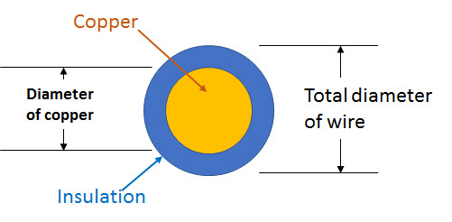
- S1 - the conductor cross-sectional area in ratio to the total wire cross sectional area. This is basically the ratio of copper to total wire plus copper cross-section. S1 is selected from a look-up table based om wire gauge and thickness of the wire's insulation. The data table used is: Wire-to-Insulation Ratios and the data is retrieved by the equation: Wire_Cu-to-Insulation. See figure 1.
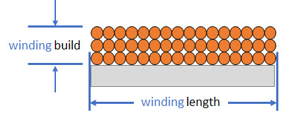
- S2 - the fill factor for the wound wire. This is basically a measure of the compactness of the wire windings being wound tightly together. See figure 2
- S3 - the effective window factor is the usable area in ratio to the total window area. Essentially this is a measure of what margins are required that can't contain the winding and open space that must be left unwound so that the device to create the winding has space to work.
- S4 - the usable window area in ration to the usable window area + Insulation
The S1Term |
 Figure 1: By Michael Bartmess |
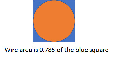
The S2"Fill Factor" TermFigure 2 shows a square winding laid evenly side-by side. This particular winding pattern forms rows and columns of wires with wire centers on a square grid. The theoretical ratio of the wire cross section to the square area in which the wire resides in a square winding is 0.785. See Figure 3 for a depiction of the ratio of a single wire to the portion of its area in the square winding. Term S2 then is a measure of the compactness referred to as the fill factor. |
 Figure 2: By Michael Bartmess |
Layered Square Lay WindingsFigure 3 shows the square lattice space in which one single wire strand lays when the windings are laid in an even square arrangement as shown in Figure 2. The arrangement of windings, of course, depends on the care and precision with which each successive winding is placed in the build. In Figure 3 it's easy to see that the maximum compactness can be calculated as 0.785 windings per unit cross-sectional space. If you make the blue rectangular space in which the circular wire resides a unit square -- in other words, 1 unit on a side, then the radius of the theoretically perfect winding has a diameter of 1 unit also. Find the are of the 1 unit diameter wire using the vCalc equation: Area of a circle Since the radius is half the unit diameter, the are is just: Area=π⋅r2=π⋅0.52=0.78539816 , which is about 0.785. So, the best you can do in building windings in a square cross-sectional arrangement is about a ratio of 0.785 windings to unit space. |
 Figure 3: By Michael Bartmess |
Layered Hexagonal Lay Windings
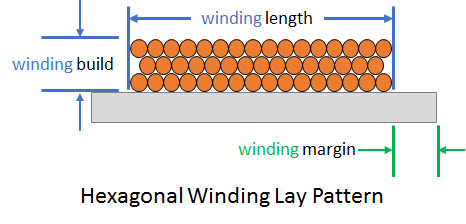
This square winding of Figure 2 and Figure 3 is not the most compact you can make windings. If you arrange them as in Figure 4, you get a lattice in cross section where the wire centers lay in a hexagonal pattern. This is the most optimal packing of the windings and produces a fill factor of approximately 0.866.

Figure 3: By Michael Bartmess
The S3"Effective Window" Term
On certain windings there is a need for a margin area that doesn't hold windings. This margin area has become industry standardized for combinations of transformer configuration and wire gauge.
The winding margin shown in Figure 3 at least partly defines a boundary are that cannot be utilized for windings.
Because the specific design can vary, we leave it in this vCalc equation for the user to determine what value for the S3 Effective Window term is.
Here are some guideline examples to use in choosing a value for S3:
- A single bobbin design typically offers an effective area,S3 between 0.835 to 0.929 for laminations.
- A single bobbin design typically offers an effective area,S3 between 0.55 to 0.75 for ferrites.
- A two bobbin configuration offers an effective area, S3, between 0.687 to 0.873 for the type C cores.
- To wind a toroidal core there has to be room to allow the free passage of a shuttle. Typically this configuration results in a effective area, S3, around 0.75.
The S4"Insulation Factor" Term
The Insulation Factor term, S4, defines how much of the usable window space is actually being used for insulation.
S4is basically the ratio of the usable window area to the window area with decreased by insulation. S4 i soften approximated with the value of 1.
See Also
Equations and Data Items
Collections
- Comments
- Attachments
- Stats
No comments |
