
Transformer Design Collection
Tags | |
UUID | 1be591b9-f145-11e9-8682-bc764e2038f2 |
The equations, constants, calculators and collections shown below are all related to the design of a transformer.
See the many related electrical equations in vCalc's Electrical Library.
What is a Transformer
A transformer transfers electrical energy between electrical circuits through electromagnetic induction. Electromagnetic induction produces an electromotive force, the force that drives a current in a conductor when the conductor is exposed to time varying magnetic fields.
Transformers are used to increase or decrease the alternating voltages in electric power applications, thus they "transform" the voltage from one voltage level to another voltage level.

A varying current in the transformer's primary winding creates a varying magnetic flux in the transformer core and a varying field impinging on the transformer's secondary winding. See Figure 1
Varying magnetic field in a conductor causes motion of charge thus inducing voltage in the conductor. In the transformer varying magnetic field at the secondary winding induces a varying electromotive force (EMF) or voltage in the secondary winding due to electromagnetic induction.
In other words, the varying current in the primary winding creates varying magnetic field in the secondary winding and that, in turn creates voltage in the secondary winding.
Since we distribute power over large distances using high voltage alternating current delivery wires, it is necessary to step the voltage down when it arrives at your home. Thus transformers play an essential part in residential power delivery, among a myriad of other uses.
Transformer Design Elements
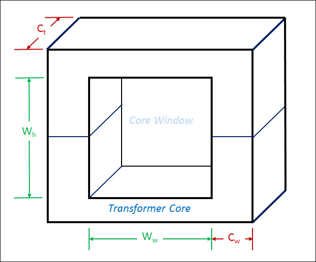
Figure 2 shows the dimensions of a simple transformer's core design. The Core is the component of the transformer in which the magnetic flux is concentrated and around which the winding from from the primary and secondary circuits are wound. The Core Geometry is a key transformer design element and is expressed in units of `"cm"^5`.
Equations
- Transformer Power Handled MichaelBartmess Use Equation
- Transformer Core Geometry - Kg MichaelBartmess Use Equation
- Transformer Metric Ke MichaelBartmess Use Equation
- Magnetic Flux Density MichaelBartmess Use Equation
- Flux Density from Field Strength MichaelBartmess Use Equation
- Magnetic Flux Unit Conversion MichaelBartmess Use Equation
- Magnetic Flux Density Unit Conversion KurtHeckman Use Equation
- Coil Magnetic Energy EdwardOmbui Use Equation
- Stored Magnetic Energy (Volume) vCollections Use Equation
- Magnetic Field (solenoid) vCollections Use Equation
- Stored Magnetic Energy vCollections Use Equation
- Phase Angle (AC) MichaelBartmess Use Equation
- Power Factor MichaelBartmess Use Equation
- Peak Voltage MichaelBartmess Use Equation
- Inductance per unit length Carol Use Equation
- Inductance of a coil TeddyCamelus Use Equation
- Relative Permittivity Lookup MichaelBartmess Use Equation
- Inductance for a Solenoid MichaelBartmess Use Equation
- Transformer Design - Core Size DavidC Use Equation
- Transformer Air Gap MichaelBartmess Use Equation
- Winding Resistance MichaelBartmess Use Equation
- DC Resistance of a Wire MichaelBartmess Use Equation
- Power Loss Due to Wire Resistance MichaelBartmess Use Equation
- Winding Porosity MichaelBartmess Use Equation
- Transformer Design - Impedance Matching Jeff Use Equation
- Transformer Window Utilization Factor Ku MichaelBartmess Use Equation
- Transformer Electrical Magnetic Operating Factor Ke MichaelBartmess Use Equation
- vVoltage MichaelBartmess Use Equation
- vElectric Charge MichaelBartmess Use Equation
- Electric Field Intensity Unit Conversion MichaelBartmess Use Equation
- V (Ohm's Law) MichaelBartmess Use Equation
- Voltage from Current and Power DavidC Use Equation
- Voltage from Current and Resistance DavidC Use Equation
- Resistance from Power and Potential DavidC Use Equation
- Power from Voltage and Resistance DavidC Use Equation
- Voltage using angular velocity vCollections Use Equation
- Time Averaged Power (V,R) MichaelBartmess Use Equation
- Time Averaged Power (V, I) MichaelBartmess Use Equation
- Electric Current Unit Conversion MichaelBartmess Use Equation
- Capacitance Unit Conversion MichaelBartmess Use Equation
- Energy Density of Magnetic Field MichaelBartmess Use Equation
- Magnetomotive Force MichaelBartmess Use Equation
- Magnetic Field MichaelBartmess Use Equation
- Flux Density[mu,H] MichaelBartmess Use Equation
Data Items
- Magnetic Flux Quantum (emag) MichaelBartmess Use Data Item
- Comments
- Attachments
- Stats
No comments |