LM 30.4 Summary Collection
Tags | |
UUID | 1eee9a07-f145-11e9-8682-bc764e2038f2 |
30.4 Summary by Benjamin Crowell, Light and Matter licensed under the Creative Commons Attribution-ShareAlike license.
Summary
Vocabulary
focal length — a property of a lens or mirror, equal to the distance from the lens or mirror to the image it forms of an object that is infinitely far away
Notation
ff — the focal length
dodo — the distance of the object from the mirror
didi — the distance of the image from the mirror
θfθf — the focal angle, defined as 1/f1/f
θoθo — the object angle, defined as 1/do1/do
θiθi — the image angle, defined as 1/di1/di
Other Notation
f>0f>0 — describes a converging lens or mirror; in this book, all focal lengths are positive, so there is no such implication
f<0f<0 — describes a diverging lens or mirror; in this book, all focal lengths are positive
M<0M<0 — indicates an inverted image; in this book, all magnifications are positive
Summary
Every lens or mirror has a property called the focal length, which is defined as the distance from the lens or mirror to the image it forms of an object that is infinitely far away. A stronger lens or mirror has a shorter focal length.
The relationship between the locations of an object and its image formed by a lens or mirror can always be expressed by equations of the form
θf=±θi±θoθf=±θi±θo
1f=±1di±1do1f=±1di±1do.
The choice of plus and minus signs depends on whether we are dealing with a lens or a mirror, whether the lens or mirror is converging or diverging, and whether the image is real or virtual. A method for determining the plus and minus signs is as follows:
- Use ray diagrams to decide whether θiθi and θoθo vary in the same way or in opposite ways. Based on this, decide whether the two signs in the equation are the same or opposite. If the signs are opposite, go on to step 2 to determine which is positive and which is negative.
2. If the signs are opposite, we need to decide which is the positive one and which is the negative. Since the focal angle is never negative, the smaller angle must be the one with a minus sign.
Once the correct form of the equation has been determined, the magnification can be found via the equation
This equation expresses the idea that the entire image-world is shrunk consistently in all three dimensions.
Homework Problems
Key
√√ A computerized answer check is available online.
∫∫ A problem that requires calculus.
⋆⋆ A difficult problem.
1. Apply the equation M=didoM=dido to the case of a flat mirror.
2. (solution in the pdf version of the book) Use the method described in the text to derive the equation relating object distance to image distance for the case of a virtual image produced by a converging mirror.
3. (a) Make up a numerical example of a virtual image formed by a converging mirror with a certain focal length, and determine the magnification. (You will need the result of problem 2.) Make sure to choose values of dodo and ff that would actually produce a virtual image, not a real one. Now change the location of the object a little bit and redetermine the magnification, showing that it changes. At my local department store, the cosmetics department sells hand mirrors advertised as giving a magnification of 5 times. How would you interpret this?
(b) Suppose a Newtonian telescope is being used for astronomical observing. Assume for simplicity that no eyepiece is used, and assume a value for the focal length of the mirror that would be reasonable for an amateur instrument that is to fit in a closet. Is the angular magnification different for objects at different distances? For example, you could consider two planets, one of which is twice as far as the other.
4. (a) Find a case where the magnification of a curved mirror is infinite. Is the angular magnification infinite from any realistic viewing position? (b) Explain why an arbitrarily large magnification can't be achieved by having a sufficiently small value of dodo.
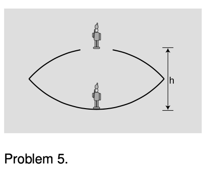
 5. The figure shows a device for constructing a realistic optical illusion. Two mirrors of equal focal length are put against each other with their silvered surfaces facing inward. A small object placed in the bottom of the cavity will have its image projected in the air above. The way it works is that the top mirror produces a virtual image, and the bottom mirror then creates a real image of the virtual image. (a) Show that if the image is to be positioned as shown, at the mouth of the cavity, then the focal length of the mirrors is related to the dimension hh via the equation
1f=1h+1h+(1h1f)-1.1f=1h+1h+(1h1f)−1.
(b) Restate the equation in terms of a single variable x=h/fx=h/f, and show that there are two solutions for xx. Which solution is physically consistent with the assumptions of the calculation? ⋆⋆
6. A concave surface that reflects sound waves can act just like a converging mirror. Suppose that, standing near such a surface, you are able to find a point where you can place your head so that your own whispers are focused back on your head, so that they sound loud to you. Given your distance to the surface, what is the surface's focal length?
7. Find the focal length of the mirror in problem 5 in chapter 28. √√
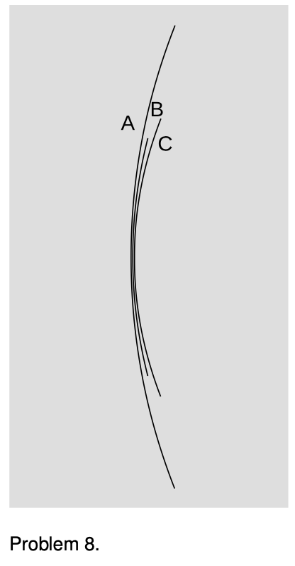
 8. Rank the focal lengths of the mirrors in the figure, from shortest to longest. Explain.
9. (a) A converging mirror is being used to create a virtual image. What is the range of possible magnifications? (b) Do the same for the other types of images that can be formed by curved mirrors (both converging and diverging).
10. (solution in the pdf version of the book) (a) A converging mirror with a focal length of 20 cm is used to create an image, using an object at a distance of 10 cm. Is the image real, or is it virtual? (b) How about f=20f=20 cm and do=30do=30 cm? (c) What if it was a diverging mirror with f=20f=20 cm and do=10do=10 cm? (d) A diverging mirror with f=20f=20 cm and do=30do=30 cm?
11. A diverging mirror of focal length ff is fixed, and faces down. An object is dropped from the surface of the mirror, and falls away from it with acceleration gg. The goal of the problem is to find the maximum velocity of the image.
(a) Describe the motion of the image verbally, and explain why we should expect there to be a maximum velocity.
(b) Use arguments based on units to determine the form of the solution, up to an unknown unitless multiplicative constant.
(c) Complete the solution by determining the unitless constant. ∫∫
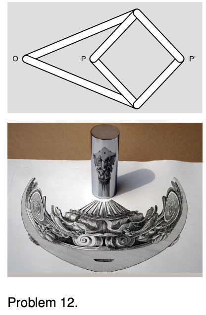
 12. A mechanical linkage is a device that changes one type of motion into another. The most familiar example occurs in a gasoline car's engine, where a connecting rod changes the linear motion of the piston into circular motion of the crankshaft. The top panel of the figure shows a mechanical linkage invented by Peaucellier in 1864, and independently by Lipkin around the same time. It consists of six rods joined by hinges, the four short ones forming a rhombus. Point OO is fixed in space, but the apparatus is free to rotate about OO. Motion at PP is transformed into a different motion at P′ (or vice versa).
Geometrically, the linkage is a mechanical implementation of the ancient problem of inversion in a circle. Considering the case in which the rhombus is folded flat, let the k be the distance from O to the point where P and P′ coincide. Form the circle of radius k with its center at O. As P and P′ move in and out, points on the inside of the circle are always mapped to points on its outside, such that rr′=k2. That is, the linkage is a type of analog computer that exactly solves the problem of finding the inverse of a number r. Inversion in a circle has many remarkable geometrical properties, discussed in H.S.M. Coxeter, Introduction to Geometry, Wiley, 1961. If a pen is inserted through a hole at P, and P′ is traced over a geometrical figure, the Peaucellier linkage can be used to draw a kind of image of the figure.
A related problem is the construction of pictures, like the one in the bottom panel of the figure, called anamorphs. The drawing of the column on the paper is highly distorted, but when the reflecting cylinder is placed in the correct spot on top of the page, an undistorted image is produced inside the cylinder. (Wide-format movie technologies such as Cinemascope are based on similar principles.)
Show that the Peaucellier linkage does not convert correctly between an image and its anamorph, and design a modified version of the linkage that does. Some knowledge of analytic geometry will be helpful.
Object and image distance
Equipment:
- optical benches
- converging mirrors
- illuminated objects
1. Set up the optical bench with the mirror at zero on the centimeter scale. Set up the illuminated object on the bench as well.
2. Each group will locate the image for their own value of the object distance, by finding where a piece of paper has to be placed in order to see the image on it. (The instructor will do one point as well.) Note that you will have to tilt the mirror a little so that the paper on which you project the image doesn't block the light from the illuminated object.
Is the image real or virtual? How do you know? Is it inverted, or uninverted?
Draw a ray diagram.
3. Measure the image distance and write your result in the table on the board. Do the same for the magnification.
4. What do you notice about the trend of the data on the board? Draw a second ray diagram with a different object distance, and show why this makes sense. Some tips for doing this correctly: (1) For simplicity, use the point on the object that is on the mirror's axis. (2) You need to trace two rays to locate the image. To save work, don't just do two rays at random angles. You can either use the on-axis ray as one ray, or do two rays that come off at the same angle, one above and one below the axis. (3) Where each ray hits the mirror, draw the normal line, and make sure the ray is at equal angles on both sides of the normal.
5. We will find the mirror's focal length from the instructor's data-point. Then, using this focal length, calculate a theoretical prediction of the image distance, and write it on the board next to the experimentally determined image distance.
30.4 Summary by Benjamin Crowell, Light and Matter licensed under the Creative Commons Attribution-ShareAlike license.
Calculators and Collections
Equations
- Focal Angle vCollections Use Equation
- Image Angle vCollections Use Equation
- Magnification vCollections Use Equation
- Focal Length WilliamC Use Equation
- Comments
- Attachments
- Stats
No comments |
