LM 25.5 Impedance Collection
Tags | |
UUID | 1ec36a27-f145-11e9-8682-bc764e2038f2 |
25.5 Impedance by Benjamin Crowell, Light and Matter licensed under the Creative Commons Attribution-ShareAlike license.
25.5 Impedance
So far we have been thinking in terms of the free oscillations of a circuit. This is like a mechanical oscillator that has been kicked but then left to oscillate on its own without any external force to keep the vibrations from dying out. Suppose an LRC circuit is driven with a sinusoidally varying voltage, such as will occur when a radio tuner is hooked up to a receiving antenna. We know that a current will flow in the circuit, and we know that there will be resonant behavior, but it is not necessarily simple to relate current to voltage in the most general case. Let’s start instead with the special cases of LRC circuits consisting of only a resistance, only a capacitance, or only an inductance. We are interested only in the steady-state response.
The purely resistive case is easy. Ohm’s law gives
I=VR.
 In the purely capacitive case, the relation V=qC lets us calculate
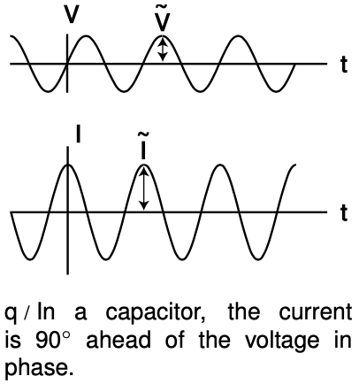
If the voltage varies as, for example, V(t)=˜Vsin(ωt), then it can be shown using calculus that the current will be I(t)=ωC˜Vcos(ωt), so the maximum current is ˜I˜=ωC˜V. By analogy with Ohm's law, we can then write
where the quantity
ZC=1ωC, [impedance of a capacitor]
having units of ohms, is called the impedance of the capacitor at this frequency. Note that it is only the maximum current, ˜I, that is proportional to the maximum voltage, ˜V, so the capacitor is not behaving like a resistor. The maxima of V and I occur at different times, as shown in figure q. It makes sense that the impedance becomes infinite at zero frequency. Zero frequency means that it would take an infinite time before the voltage would change by any amount. In other words, this is like a situation where the capacitor has been connected across the terminals of a battery and been allowed to settle down to a state where there is constant charge on both terminals. Since the electric fields between the plates are constant, there is no energy being added to or taken out of the field. A capacitor that can't exchange energy with any other circuit component is nothing more than a broken (open) circuit.
self-check:
Why can't a capacitor have its impedance printed on it along with its capacitance?
(answer in the back of the PDF version of the book)
 Similar math gives
ZL=ωL [impedance of an inductor]
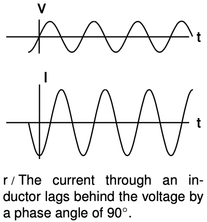
for an inductor. It makes sense that the inductor has lower impedance at lower frequencies, since at zero frequency there is no change in the magnetic field over time. No energy is added to or released from the magnetic field, so there are no induction effects, and the inductor acts just like a piece of wire with negligible resistance. The term “choke” for an inductor refers to its ability to “choke out” high frequencies.
The phase relationships shown in figures q and r can be remembered using my own mnemonic, “eVIL,” which shows that the voltage (V) leads the current (I) in an inductive circuit, while the opposite is true in a capacitive one. A more traditional mnemonic is “ELI the ICE man,” which uses the notation E for emf, a concept closely related to voltage.
Example 7: Low-pass and high-pass filters
An LRC circuit only responds to a certain range (band) of frequencies centered around its resonant frequency. As a filter, this is known as a band pass filter. If you turn down both the bass and the treble on your stereo, you have created a band pass filter.
To create a high-pass or low-pass filter, we only need to insert a capacitor or inductor, respectively, in series. For instance, a very basic surge protector for a computer could be constructed by inserting an inductor in series with the computer. The desired 60 Hz power from the wall is relatively low in frequency, while the surges that can damage your computer show much more rapid time variation. Even if the surges are not sinusoidal signals, we can think of a rapid “spike” qualitatively as if it was very high in frequency - like a high-frequency sine wave, it changes very rapidly.
Inductors tend to be big, heavy, expensive circuit elements, so a simple surge protector would be more likely to consist of a capacitor in parallel with the computer. (In fact one would normally just connect one side of the power circuit to ground via a capacitor.) The capacitor has a very high impedance at the low frequency of the desired 60 Hz signal, so it siphons off very little of the current. But for a high-frequency signal, the capacitor's impedance is very small, and it acts like a zero-impedance, easy path into which the current is diverted.
The main things to be careful about with impedance are that (1) the concept only applies to a circuit that is being driven sinusoidally, (2) the impedance of an inductor or capacitor is frequency-dependent, and (3) impedances in parallel and series don't combine according to the same rules as resistances. It is possible, however, to get get around the third limitation, as discussed in subsection .
Discussion Questions
A Figure q on page 726 shows the voltage and current for a capacitor. Sketch the q-t graph, and use it to give a physical explanation of the phase relationship between the voltage and current. For example, why is the current zero when the voltage is at a maximum or minimum?
B Relate the features of the graph in figure r on page 727 to the story told in cartoons in figure m/2-3 on page 722.
Homework Problems
1. If an FM radio tuner consisting of an LRC circuit contains a 1.0 μH inductor, what range of capacitances should the variable capacitor be able to provide? √
2. (a) Show that the equation V=|LΔIΔt| has the right units.
(b) Verify that RC has units of time.
(c) Verify that L/R has units of time.
3. Find the energy stored in a capacitor in terms of its capacitance and the voltage difference across it. √
4. Find the inductance of two identical inductors in parallel.
5. The wires themselves in a circuit can have resistance, inductance, and capacitance. Would “stray” inductance and capacitance be most important for low-frequency or for high-frequency circuits? For simplicity, assume that the wires act like they're in series with an inductor or capacitor.
6. (a) Find the capacitance of two identical capacitors in series.
(b) Based on this, how would you expect the capacitance of a parallel-plate capacitor to depend on the distance between the plates?
7. Find the capacitance of the surface of the earth, assuming there is an outer spherical “plate” at infinity. (In reality, this outer plate would just represent some distant part of the universe to which we carried away some of the earth's charge in order to charge up the earth.) √
8. Starting from the relation for the voltage difference across an inductor, show that an inductor has an impedance equal to L?.
25.5 Impedance by Benjamin Crowell, Light and Matter licensed under the Creative Commons Attribution-ShareAlike license.
Calculators and Collections
Equations
- Current using Capacitance and Voltage vCollections Use Equation
- Current using the Impedance of a Capacitor vCollections Use Equation
- Voltage across a Capacitor vCollections Use Equation
- Current vCollections Use Equation
- Current using capacitance vCollections Use Equation
- Voltage using angular velocity vCollections Use Equation
- Current using angular velocity vCollections Use Equation
- Impedance of a capacitor vCollections Use Equation
- Impedance of an Inductor vCollections Use Equation
- Current from Potential and Resistance DavidC Use Equation
- Voltage using Inductance WilliamC Use Equation
- Comments
- Attachments
- Stats
No comments |
