LM 30.2 Other cases with curved mirrors Collection
30.2 Other cases with curved mirrors by Benjamin Crowell, Light and Matter licensed under the Creative Commons Attribution-ShareAlike license.
30.2 Other cases with curved mirrors
The equation di=(1f−1do)−1 can easily produce a negative result, but we have been thinking of di as a distance, and distances can't be negative. A similar problem occurs with θi=θf−θo for θo>θf. What's going on here?
The interpretation of the angular equation is straightforward. As we bring the object closer and closer to the image, θo gets bigger and bigger, and eventually we reach a point where θo=θf and θi=0. This large object angle represents a bundle of rays forming a cone that is very broad, so broad that the mirror can no longer bend them back so that they reconverge on the axis. The image angle θi=0 represents an outgoing bundle of rays that are parallel. The outgoing rays never cross, so this is not a real image, unless we want to be charitable and say that the rays cross at infinity. If we go on bringing the object even closer, we get a virtual image.

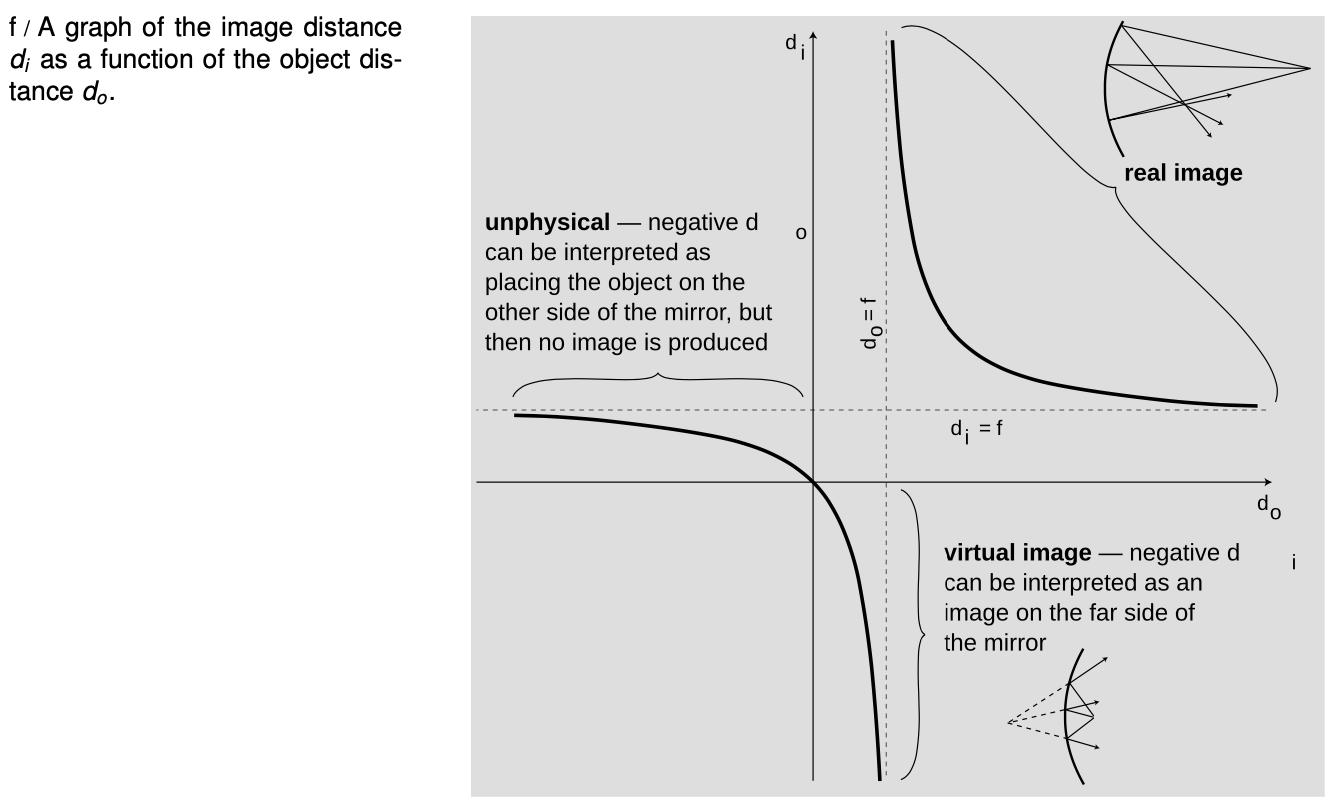
To analyze the distance equation, let's look at a graph of di as a function of do. The branch on the upper right corresponds to the case of a real image. Strictly speaking, this is the only part of the graph that we've proven corresponds to reality, since we never did any geometry for other cases, such as virtual images. As discussed in the previous section, making do bigger causes di to become smaller, and vice-versa.
Letting do be less thanf is equivalent to θo>θf: a virtual image is produced on the far side of the mirror. This is the first example of Wigner's “unreasonable effectiveness of mathematics” that we have encountered in optics. Even though our proof depended on the assumption that the image was real, the equation we derived turns out to be applicable to virtual images, provided that we either interpret the positive and negative signs in a certain way, or else modify the equation to have different positive and negative signs.
self-check:
Interpret the three places where, in physically realistic parts of the graph, the graph approaches one of the dashed lines. [This will come more naturally if you have learned the concept of limits in a math class.]
(answer in the back of the PDF version of the book)
Example 4: A flat mirror
We can even apply the equation to a flat mirror. As a sphere gets bigger and bigger, its surface is more and more gently curved. The planet Earth is so large, for example, that we cannot even perceive the curvature of its surface. To represent a flat mirror, we let the mirror's radius of curvature, and its focal length, become infinite. Dividing by infinity gives zero, so we have
1do=−1di,
or
do=−di.
If we interpret the minus sign as indicating a virtual image on the far side of the mirror from the object, this makes sense.
It turns out that for any of the six possible combinations of real or virtual images formed by converging or diverging lenses or mirrors, we can apply equations of the form
θf=θi+θo
and
1f=1di+1do,
with only a modification of plus or minus signs. There are two possible approaches here. The approach we have been using so far is the more popular approach in American textbooks: leave the equation the same, but attach interpretations to the resulting negative or positive values of the variables. The trouble with this approach is that one is then forced to memorize tables of sign conventions, e.g., that the value of di should be negative when the image is a virtual image formed by a converging mirror. Positive and negative signs also have to be memorized for focal lengths. Ugh! It's highly unlikely that any student has ever retained these lengthy tables in his or her mind for more than five minutes after handing in the final exam in a physics course. Of course one can always look such things up when they are needed, but the effect is to turn the whole thing into an exercise in blindly plugging numbers into formulas.
As you have gathered by now, there is another method which I think is better, and which I'll use throughout the rest of this book. In this method, all distances and angles are positive by definition, and we put in positive and negative signs in the equations depending on the situation. (I thought I was the first to invent this method, but I've been told that this is known as the European sign convention, and that it's fairly common in Europe.) Rather than memorizing these signs, we start with the generic equations
1f=±1di±1do,
and then determine the signs by a two-step method that depends on ray diagrams. There are really only two signs to determine, not four; the signs in the two equations match up in the way you'd expect. The method is as follows:
1. Use ray diagrams to decide whether θo and θi vary in the same way or in opposite ways. (In other words, decide whether making θo greater results in a greater value of θi or a smaller one.) Based on this, decide whether the two signs in the angle equation are the same or opposite. If the signs are opposite, go on to step 2 to determine which is positive and which is negative.
2. If the signs are opposite, we need to decide which is the positive one and which is the negative. Since the focal angle is never negative, the smaller angle must be the one with a minus sign.
In step 1, many students have trouble drawing the ray diagram correctly. For simplicity, you should always do your diagram for a point on the object that is on the axis of the mirror, and let one of your rays be the one that is emitted along the axis and reflected straight back on itself, as in the figures in section 30.1. As shown in figure a/4 in section 30.1, there are four angles involved: two at the mirror, one at the object (θo), and one at the image (θi). Make sure to draw in the normal to the mirror so that you can see the two angles at the mirror. These two angles are equal, so as you change the object position, they fan out or fan in, like opening or closing a book. Once you've drawn this effect, you should easily be able to tell whether θo and θi change in the same way or in opposite ways.
 Although focal lengths are always positive in the method used in this book, you should be aware that diverging mirrors and lenses are assigned negative focal lengths in the other method, so if you see a lens labeled f=−30cm, you'll know what it means.
Example 5: An anti-shoplifting mirror
⇒ Convenience stores often install a diverging mirror so that the clerk has a view of the whole store and can catch shoplifters. Use a ray diagram to show that the image is reduced, bringing more into the clerk's field of view. If the focal length of the mirror is 3.0 m, and the mirror is 7.0 m from the farthest wall, how deep is the image of the store?
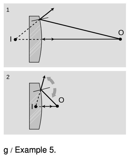
⇒ As shown in ray diagram g/1, di is less than do. The magnification, M=dido, will be less than one, i.e., the image is actually reduced rather than magnified.
Apply the method outlined above for determining the plus and minus signs. Step 1: The object is the point on the opposite wall. As an experiment, g/2, move the object closer. I did these drawings using illustration software, but if you were doing them by hand, you'd want to make the scale much larger for greater accuracy. Also, although I split figure g into two separate drawings in order to make them easier to understand, you're less likely to make a mistake if you do them on top of each other.
The two angles at the mirror fan out from the normal. Increasing θo has clearly made θi larger as well. (All four angles got bigger.) There must be a cancellation of the effects of changing the two terms on the right in the same way, and the only way to get such a cancellation is if the two terms in the angle equation have opposite signs:
`theta_f = +theta_i - theta_o
or
`theta_f = -theta_i + theta_o.
Step 2: Now which is the positive term and which is negative? Since the image angle is bigger than the object angle, the angle equation must be
θf=θi−θo,
in order to give a positive result for the focal angle. The signs of the distance equation behave the same way:
1f=1di−1do.
Solving for di, we find
di=(1f−1do)−1
=2.1m.
The image of the store is reduced by a factor of 2.1/7.0=0.3, i.e., it is smaller by 70%.
Example 6: A shortcut for real images
In the case of a real image, there is a shortcut for step 1, the determination of the signs. In a real image, the rays cross at both the object and the image. We can therefore time-reverse the ray diagram, so that all the rays are coming from the image and reconverging at the object. Object and image swap roles. Due to this time-reversal symmetry, the object and image cannot be treated differently in any of the equations, and they must therefore have the same signs. They are both positive, since they must add up to a positive result.
30.2 Other cases with curved mirrors by Benjamin Crowell, Light and Matter licensed under the Creative Commons Attribution-ShareAlike license.
Calculators and Collections
Equations
- Focal Angle vCollections Use Equation
- Magnification vCollections Use Equation
- Focal Length WilliamC Use Equation
- Comments
- Attachments
- Stats
No comments |
