LM 21.6 Resistance Collection
Tags | |
UUID | 1e899174-f145-11e9-8682-bc764e2038f2 |
21.6 Resistance by Benjamin Crowell, Light and Matter licensed under the Creative Commons Attribution-ShareAlike license.
21.6 Resistance
Resistance
So far we have simply presented it as an observed fact that a battery-and-bulb circuit quickly settles down to a steady flow, but why should it? Newton's second law, A=FM, would seem to predict that the steady forces on the charged particles should make them whip around the circuit faster and faster. The answer is that as charged particles move through matter, there are always forces, analogous to frictional forces, that resist the motion. These forces need to be included in Newton's second law, which is really A=FtotalM, not A=FM. If, by analogy, you push a crate across the floor at constant speed, i.e., with zero acceleration, the total force on it must be zero. After you get the crate going, the floor's frictional force is exactly canceling out your force. The chemical energy stored in your body is being transformed into heat in the crate and the floor, and no longer into an increase in the crate's kinetic energy. Similarly, the battery's internal chemical energy is converted into heat, not into perpetually increasing the charged particles' kinetic energy. Changing energy into heat may be a nuisance in some circuits, such as a computer chip, but it is vital in a lightbulb, which must get hot enough to glow. Whether we like it or not, this kind of heating effect is going to occur any time charged particles move through matter.
What determines the amount of heating? One flashlight bulb designed to work with a 9-volt battery might be labeled 1.0 watts, another 5.0. How does this work? Even without knowing the details of this type of friction at the atomic level, we can relate the heat dissipation to the amount of current that flows via the equation P=IΔV. If the two flashlight bulbs can have two different values of PP when used with a battery that maintains the same ΔV, it must be that the 5.0-watt bulb allows five times more current to flow through it.
 For many substances, including the tungsten from which lightbulb filaments are made, experiments show that the amount of current that will flow through it is directly proportional to the voltage difference placed across it. For an object made of such a substance, we define its electrical resistance as follows:
definition of resistance
If an object inserted in a circuit displays a current flow proportional to the voltage difference across it, then we define its resistance as the constant ratio R=ΔVI.
The units of resistance are volts/ampere, usually abbreviated as ohms, symbolized with the capital Greek letter omega, ω.
Example 7: Resistance of a lightbulb
⇒ A flashlight bulb powered by a 9-volt battery has a resistance of 10Ω. How much current will it draw?
⇒ Solving the definition of resistance for I, we find
I=VR
=0.9 V / Ω
=0.9 V / (V/A)
=0.9 A
Ohm's law states that many substances, including many solids and some liquids, display this kind of behavior, at least for voltages that are not too large. The fact that Ohm's law is called a “law” should not be taken to mean that all materials obey it, or that it has the same fundamental importance as Newton's laws, for example. Materials are called ohmic or nonohmic, depending on whether they obey Ohm's law. Although we will concentrate on ohmic materials in this book, it's important to keep in mind that a great many materials are nonohmic, and devices made from them are often very important. For instance, a transistor is a nonohmic device that can be used to amplify a signal (as in a guitar amplifier) or to store and manipulate the ones and zeroes in a computer chip.
If objects of the same size and shape made from two different ohmic materials have different resistances, we can say that one material is more resistive than the other, or equivalently that it is less conductive. Materials, such as metals, that are very conductive are said to be good conductors. Those that are extremely poor conductors, for example wood or rubber, are classified as insulators. There is no sharp distinction between the two classes of materials. Some, such as silicon, lie midway between the two extremes, and are called semiconductors.
 On an intuitive level, we can understand the idea of resistance by making the sounds “hhhhhh” and “ffffff.” To make air flow out of your mouth, you use your diaphragm to compress the air in your chest. The pressure difference between your chest and the air outside your mouth is analogous to a voltage difference. When you make the “h” sound, you form your mouth and throat in a way that allows air to flow easily. The large flow of air is like a large current. Dividing by a large current in the definition of resistance means that we get a small resistance. We say that the small resistance of your mouth and throat allows a large current to flow. When you make the “f” sound, you increase the resistance and cause a smaller current to flow.
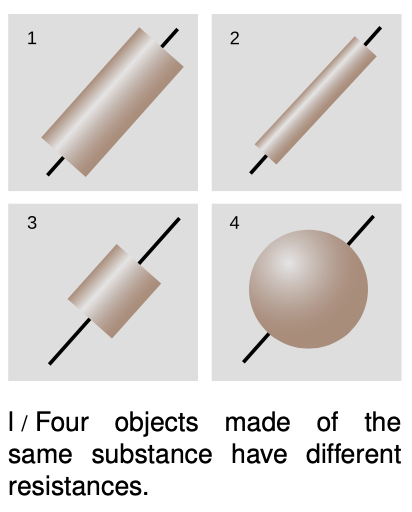
Note that although the resistance of an object depends on the substance it is made of, we cannot speak simply of the “resistance of gold” or the “resistance of wood.” Figure l shows four examples of objects that have had wires attached at the ends as electrical connections. If they were made of the same substance, they would all nevertheless have different resistances because of their different sizes and shapes. A more detailed discussion will be more natural in the context of the following chapter, but it should not be too surprising that the resistance of l/2 will be greater than that of l/1 --- the image of water flowing through a pipe, however incorrect, gives us the right intuition. Object l/3 will have a smaller resistance than l/1 because the charged particles have less of it to get through.
Superconductors
 All materials display some variation in resistance according to temperature (a fact that is used in thermostats to make a thermometer that can be easily interfaced to an electric circuit). More spectacularly, most metals have been found to exhibit a sudden change to zero resistance when cooled to a certain critical temperature. They are then said to be superconductors. Currently, the most important practical application of superconductivity is in medical MRI (magnetic resonance imaging) scanners. The mechanism of MRI is explained on p. 471, but the important point for now is that when your body is inserted into one of these devices, you are being immersed in an extremely strong magnetic field produced by electric currents flowing through the coiled wires of an electromagnet. If these wires were not superconducting, they would instantly burn up because of the heat generated by their resistance.
There are many other potential applications for superconductors, but most of these, such as power transmission, are not currently economically feasible because of the extremely low temperatures required for superconductivity to occur.
However, it was discovered in 1986 that certain ceramics are superconductors at less extreme temperatures. The technological barrier is now in finding practical methods for making wire out of these brittle materials. Wall Street is currently investing billions of dollars in developing superconducting devices for cellular phone relay stations based on these materials.
There is currently no satisfactory theory of superconductivity in general, although superconductivity in metals is understood fairly well. Unfortunately I have yet to find a fundamental explanation of superconductivity in metals that works at the introductory level.
Constant voltage throughout a conductor
The idea of a superconductor leads us to the question of how we should expect an object to behave if it is made of a very good conductor. Superconductors are an extreme case, but often a metal wire can be thought of as a perfect conductor, for example if the parts of the circuit other than the wire are made of much less conductive materials. What happens if R equals zero in the equation R=VI? The result of dividing two numbers can only be zero if the number on top equals zero. This tells us that if we pick any two points in a perfect conductor, the voltage difference between them must be zero. In other words, the entire conductor must be at the same voltage.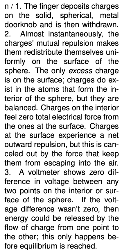

Constant voltage means that no work would be done on a charge as it moved from one point in the conductor to another. If zero work was done only along a certain path between two specific points, it might mean that positive work was done along part of the path and negative work along the rest, resulting in a cancellation. But there is no way that the work could come out to be zero for all possible paths unless the electrical force on a charge was in fact zero at every point. Suppose, for example, that you build up a static charge by scuffing your feet on a carpet, and then you deposit some of that charge onto a doorknob, which is a good conductor. How can all that charge be in the doorknob without creating any electrical force at any point inside it? The only possible answer is that the charge moves around until it has spread itself into just the right configuration so that the forces exerted by all the little bits of excess surface charge on any charged particle within the doorknob exactly cancel out.
 We can explain this behavior if we assume that the charge placed on the doorknob eventually settles down into a stable equilibrium. Since the doorknob is a conductor, the charge is free to move through it. If it was free to move and any part of it did experience a nonzero total force from the rest of the charge, then it would move, and we would not have an equilibrium.
Excess charge placed on a conductor, once it reaches its equilibrium configuration, is entirely on the surface, not on the interior. This should be intuitively reasonable in figure n, for example, since the charges are all repelling each other. A proof is given in example 15 on p. 640.
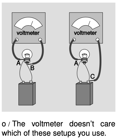
Since wires are good conductors, constancy of voltage throughout a conductor provides a convenient freedom in hooking up a voltmeter to a circuit. In figure o, points B and C are on the same piece of conducting wire, so VB=VC. Measuring VB-VA gives the same result as measuring VC-VA.
Example 8: The lightning rod
 Suppose you have a pear-shaped conductor like the one in figure p/1. Since the pear is a conductor, there are free charges everywhere inside it. Panels 1 and 2 of the figure show a computer simulation with 100 identical electric charges. In 1, the charges are released at random positions inside the pear. Repulsion causes them all to fly outward onto the surface and then settle down into an orderly but nonuniform pattern.
We might not have been able to guess the pattern in advance, but we can verify that some of its features make sense. For example, charge A has more neighbors on the right than on the left, which would tend to make it accelerate off to the left. But when we look at the picture as a whole, it appears reasonable that this is prevented by the larger number of more distant charges on its left than on its right.
There also seems to be a pattern to the nonuniformity: the charges collect more densely in areas like B, where the surface is strongly curved, and less densely in flatter areas like C.
To understand the reason for this pattern, consider p/3. Two conducting spheres are connected by a conducting wire. Since the whole apparatus is conducting, it must all be at one voltage. As shown in problem 43 on p. 608, the density of charge is greater on the smaller sphere. This is an example of a more general fact observed in p/2, which is that the charge on a conductor packs itself more densely in areas that are more sharply curved.
Similar reasoning shows why Benjamin Franklin used a sharp tip when he invented the lightning rod. The charged stormclouds induce positive and negative charges to move to opposite ends of the rod. At the pointed upper end of the rod, the charge tends to concentrate at the point, and this charge attracts the lightning. The same effect can sometimes be seen when a scrap of aluminum foil is inadvertently put in a microwave oven. Modern experiments (Moore et al., Journal of Applied Meteorology 39 (1999) 593) show that although a sharp tip is best at starting a spark, a more moderate curve, like the right-hand tip of the pear in this example, is better at successfully sustaining the spark for long enough to connect a discharge to the clouds.
Short circuits
So far we have been assuming a perfect conductor. What if it is a good conductor, but not a perfect one? Then we can solve for ΔV=IR. An ordinary-sized current will make a very small result when we multiply it by the resistance of a good conductor such as a metal wire. The voltage throughout the wire will then be nearly constant. If, on the other hand, the current is extremely large, we can have a significant voltage difference. This is what happens in a short- circuit: a circuit in which a low-resistance pathway connects the two sides of a voltage source. Note that this is much more specific than the popular use of the term to indicate any electrical malfunction at all. If, for example, you short-circuit a 9-volt battery as shown in figure q, you will produce perhaps a thousand amperes of current, leading to a very large value of P=IΔV. The wire gets hot!
self-check:
What would happen to the battery in this kind of short circuit?
(answer in the back of the PDF version of the book)
Resistors
Inside any electronic gadget you will see quite a few little circuit elements like the one shown in the photo. These resistors are simply a cylinder of ohmic material with wires attached to the end.
At this stage, most students have a hard time understanding why resistors would be used inside a radio or a computer. We obviously want a lightbulb or an electric stove to have a circuit element that resists the flow of electricity and heats up, but heating is undesirable in radios and computers. Without going too far afield, let's use a mechanical analogy to get a general idea of why a resistor would be used in a radio.
The main parts of a radio receiver are an antenna, a tuner for selecting the frequency, and an amplifier to strengthen the signal sufficiently to drive a speaker. The tuner resonates at the selected frequency, just as in the examples of mechanical resonance discussed in chapter 18. The behavior of a mechanical resonator depends on three things: its inertia, its stiffness, and the amount of friction or damping. The first two parameters locate the peak of the resonance curve, while the damping determines the width of the resonance. In the radio tuner we have an electrically vibrating system that resonates at a particular frequency. Instead of a physical object moving back and forth, these vibrations consist of electrical currents that flow first in one direction and then in the other. In a mechanical system, damping means taking energy out of the vibration in the form of heat, and exactly the same idea applies to an electrical system: the resistor supplies the damping, and therefore controls the width of the resonance. If we set out to eliminate all resistance in the tuner circuit, by not building in a resistor and by somehow getting rid of all the inherent electrical resistance of the wires, we would have a useless radio. The tuner's resonance would be so narrow that we could never get close enough to the right frequency to bring in the station. The roles of inertia and stiffness are played by other circuit elements we have not discusses (a capacitor and a coil).
Many electrical devices are based on electrical resistance and Ohm's law, even if they do not have little components in them that look like the usual resistor. The following are some examples.
Lightbulb
There is nothing special about a lightbulb filament --- you can easily make a lightbulb by cutting a narrow waist into a metallic gum wrapper and connecting the wrapper across the terminals of a 9-volt battery. The trouble is that it will instantly burn out. Edison solved this technical challenge by encasing the filament in an evacuated bulb, which prevented burning, since burning requires oxygen.
Polygraph
The polygraph, or “lie detector,” is really just a set of meters for recording physical measures of the subject's psychological stress, such as sweating and quickened heartbeat. The real-time sweat measurement works on the principle that dry skin is a good insulator, but sweaty skin is a conductor. Of course a truthful subject may become nervous simply because of the situation, and a practiced liar may not even break a sweat. The method's practitioners claim that they can tell the difference, but you should think twice before allowing yourself to be polygraph tested. Most U.S. courts exclude all polygraph evidence, but some employers attempt to screen out dishonest employees by polygraph testing job applicants, an abuse that ranks with such pseudoscience as handwriting analysis.
Fuse
A fuse is a device inserted in a circuit tollbooth-style in the same manner as an ammeter. It is simply a piece of wire made of metals having a relatively low melting point. If too much current passes through the fuse, it melts, opening the circuit. The purpose is to make sure that the building's wires do not carry so much current that they themselves will get hot enough to start a fire. Most modern houses use circuit breakers instead of fuses, although fuses are still common in cars and small devices. A circuit breaker is a switch operated by a coiled-wire magnet, which opens the circuit when enough current flows. The advantage is that once you turn off some of the appliances that were sucking up too much current, you can immediately flip the switch closed. In the days of fuses, one might get caught without a replacement fuse, or even be tempted to stuff aluminum foil in as a replacement, defeating the safety feature.
Voltmeter
A voltmeter is nothing more than an ammeter with an additional high-value resistor through which the current is also forced to flow. Ohm's law relates the current through the resistor is related directly to the voltage difference across it, so the meter can be calibrated in units of volts based on the known value of the resistor. The voltmeter's two probes are touched to the two locations in a circuit between which we wish to measure the voltage difference, u/2. Note how cumbersome this type of drawing is, and how difficult it can be to tell what is connected to what. This is why electrical drawing are usually shown in schematic form. Figure u/3 is a schematic representation of figure u/2.
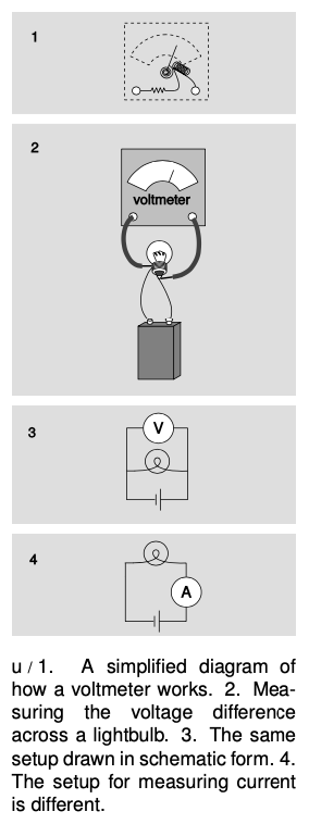 The setups for measuring current and voltage are different. When we are measuring current, we are finding “how much stuff goes through,” so we place the ammeter where all the current is forced to go through it. Voltage, however, is not “stuff that goes through,” it is a measure of electrical energy. If an ammeter is like the meter that measures your water use, a voltmeter is like a measuring stick that tells you how high a waterfall is, so that you can determine how much energy will be released by each kilogram of falling water. We do not want to force the water to go through the measuring stick! The arrangement in figure u/3 is a parallel circuit: one in there are “forks in the road” where some of the current will flow one way and some will flow the other. Figure u/4 is said to be wired in series: all the current will visit all the circuit elements one after the other. We will deal with series and parallel circuits in more detail in the following chapter.
If you inserted a voltmeter incorrectly, in series with the bulb and battery, its large internal resistance would cut the current down so low that the bulb would go out. You would have severely disturbed the behavior of the circuit by trying to measure something about it.
Incorrectly placing an ammeter in parallel is likely to be even more disconcerting. The ammeter has nothing but wire inside it to provide resistance, so given the choice, most of the current will flow through it rather than through the bulb. So much current will flow through the ammeter, in fact, that there is a danger of burning out the battery or the meter or both! For this reason, most ammeters have fuses or circuit breakers inside. Some models will trip their circuit breakers and make an audible alarm in this situation, while others will simply blow a fuse and stop working until you replace it.
Discussion Questions
A In figure u/1, would it make any difference in the voltage measurement if we touched the voltmeter's probes to different points along the same segments of wire?
B Explain why it would be incorrect to define resistance as the amount of charge the resistor allows to flow.
21.6 Resistance by Benjamin Crowell, Light and Matter licensed under the Creative Commons Attribution-ShareAlike license.
Calculators and Collections
Equations
- Amount of power dissipated vCollections Use Equation
- Acceleration from Force and Mass KurtHeckman Use Equation
- Resistance from Ohm's Law MichaelBartmess Use Equation
- Current from Potential and Resistance DavidC Use Equation
- Comments
- Attachments
- Stats
No comments |
