The Camber Offset calculator computes the camber offset from vertical based on the camber angle (C) and tire height (h). 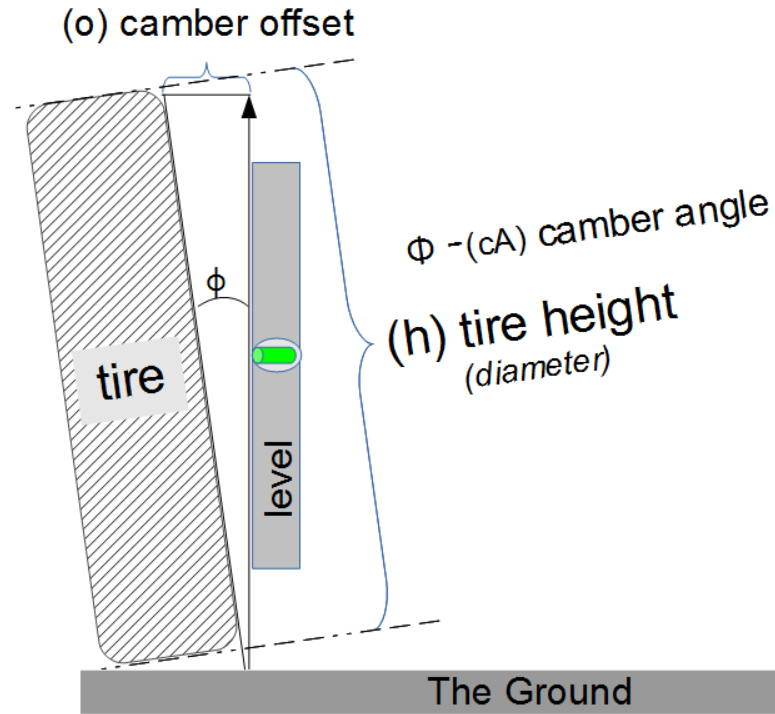 Tire Camber
INSTRUCTION: Choose units and enter the following:
- (cA) camber angle
- (h) height of the tire
Offset from Vertical (o):The calculator returns the offset (o) in inches. However, the can be automatically converted to other length units (e.g. centimeters) via the pull-down menu.
Camber Calculators
- Camber Offset: computes the tire offset from vertical using the camber angle
- Camber Angle: computes the camber angle using the camber offset
The Math
The vertical tilt of a tire is called its camber. The camber angle (C) is the measurement of that tilt. This formula provides the vertical offset (o) based the camber angle (C) and the height of the tire. The use of a bubble level and a ruler can provide a rough measurement of these two lengths.
Usage
Camber angle is the angle made by the wheels of a vehicle; specifically, it is the angle between the vertical axis of the wheels used for steering and the vertical axis of the vehicle when viewed from the front or rear. It is used in the design of steering and suspension. If the top of the wheel is farther out than the bottom (that is, away from the axle), it is called positive camber; if the bottom of the wheel is farther out than the top, it is called negative camber.
Camber angle alters the handling qualities of a particular suspension design; in particular, negative camber improves grip when cornering. This is because it places the tire at a better angle to the road, transmitting the forces through the vertical plane of the tire rather than through a shear force across it. Another reason for negative camber is that a rubber tire tends to roll on itself while cornering. The inside edge of the contact patch would begin to lift off of the ground if the tire had zero camber, reducing the area of the contact patch. This effect is compensated for by applying negative camber, maximizing the contact patch area. Note that this is only true for the outside tire during the turn; the inside tire would benefit most from positive camber.
On the other hand, for maximum straight-line acceleration, the greatest traction will be attained when the camber angle is zero and the tread is flat on the road. Proper management of camber angle is a major factor in suspension design, and must incorporate not only idealized geometric models, but also real-life behavior of the components; flex, distortion, elasticity, etc. What was once an art has now become much more scientific with the use of computers, which can optimize all of the variables mathematically instead of relying on the designer's intuitive feel and experience. As a result, the handling of even low-priced automobiles has improved dramatically in recent years.
In cars with double wishbone suspensions, camber angle may be fixed or adjustable, but in MacPherson strut suspensions, it is normally fixed. The elimination of an available camber adjustment may reduce maintenance requirements, but if the car is lowered by use of shortened springs, the camber angle will change. Excessive camber angle can lead to increased tire wear and impaired handling. Significant suspension modifications may correspondingly require that the upper control arm or strut mounting points be altered to allow for some inward or outward movement, relative to longitudinal centerline of the vehicle, for camber adjustment. Aftermarket plates with slots for strut mounts instead of just holes are available for most of the commonly modified models of cars.
Off-road vehicles such as agricultural tractors generally use positive camber. In such vehicles, the positive camber angle helps to achieve a lower steering effort. Also, some single-engined general aviation aircraft that are primarily meant to operate from unimproved surfaces, such as bush planes and cropdusters, have their taildragger gear's main wheels equipped with positive-cambered main wheels to better handle the deflection of the landing gear, as the aircraft settles on rough, unpaved airstrips.

Vehicle Calculators
- Approach (Departure) Angle: Computes the maximum angle of a ramp onto which a vehicle can climb without scraping.
- Degree to Percent Grade: Converts a grade to a degree angle.
- Camber angle - Wheel camber (tilt) calculation of angle
- Camber offset - Wheel camber (tilt) calculation of offset
- Breakover Angle: Compute maximum angle that a vehicle can drive over without the ground touching the vehicle's undercarriage.
- Time to Overtake: Computes the time for one object to overtake another.
- Distance to Overtake: Computes distance traveled to overtake another.
- Speed to Overtake: Computes the average velocity to overtake another.
- Distance at Speed: Computes the distance traveled over a period of time at a constant velocity (speed).
- Speed from Skid Marks: Estimates the speed of a vehicle based on length of skid marks.
- Braking Distance: Estimates distance to stop a vehicle based on initial velocity and braking coefficient.
- Total Stopping Distance: Computes the distance to stop a vehicle based on the initial velocity, reaction time and a braking coefficient.
- Speed from the Braking Distance: Estimates the initial speed based on the distance to stop a vehicle and the a braking coefficient.
- Used Car Price Comparison: Estimates the better value between two vehicles based on their mileage, cost and expected lifespan (miles).
- Belt Length: Computes the length of a belt that goes around two pulleys based on the pulley diameters and the distance between the axles.
- Belt Speed: Computes the speed at which a linear length of belt travels around a pulley based on the diameter of the pulley and the rotation rate.
- Pulley RPMs: Computes the RPMs of a pulley based on the belt speed and diameter of the pulley.
- 2nd Pulley RPMs: Computes the RPMs of a second pulley based on the the RPMs and Diameter of the first pulley and the diameter of the second pulley.
- 2nd Pulley Diameter: Computes the diameter of a second pulley based on the RPMs and diameter of the first pulley and the RPMs of the second pulley.
- RPM of 4th pulley on three shafts: Computes the RPMs (rotation rate) of a pulley when the RPM and Diameters are known for a series of pulleys on three axles.
- 2nd Gear RPM: Calculates the RPMs of a second gear when the RPMs and number of teeth are known for the first gear and the number of teeth of the second gear is known,
- 2nd Gear Torque: Calculates the torque of a second gear when the torque and number of teeth are known for the first gear and the number of teeth of the second gear is known,
Reference
Wikipedia - http://en.wikipedia.org/wiki/Camber_angle
Thanks to James Heckman for the technical description of tire camber.