LM 24.8 Summary Collection
24.8 Summary by Benjamin Crowell, Light and Matter licensed under the Creative Commons Attribution-ShareAlike license.
Summary
Vocabulary
magnetic field — a field of force, defined in terms of the torque exerted on a test dipole
magnetic dipole — an object, such as a current loop, an atom, or a bar magnet, that experiences torques due to magnetic forces; the strength of magnetic dipoles is measured by comparison with a standard dipole consisting of a square loop of wire of a given size and carrying a given amount of current
induction — the production of an electric field by a changing magnetic field, or vice-versa
Notation
— the magnetic field
— magnetic dipole moment
Summary
The magnetic field is defined in terms of the torque on a magnetic test dipole. It has no sources or sinks; magnetic field patterns never converge on or diverge from a point.
Relativity dictates a maximum speed limit for cause and effect. This speed is the same in all frames of reference.
Relativity requires that the magnetic and electric fields be intimately related. The principle of induction states that any changing electric field produces a magnetic field in the surrounding space, and vice-versa. These induced fields tend to form whirlpool patterns.
The most important consequence of the principle of induction is that there are no purely magnetic or purely electric waves. Electromagnetic disturbances propagate outward at as combined magnetic and electric waves, with a well-defined relationship between the magnitudes and directions of the electric and magnetic fields. These electromagnetic waves are what light is made of, but other forms of electromagnetic waves exist besides visible light, including radio waves, x-rays, and gamma rays.
Homework Problems
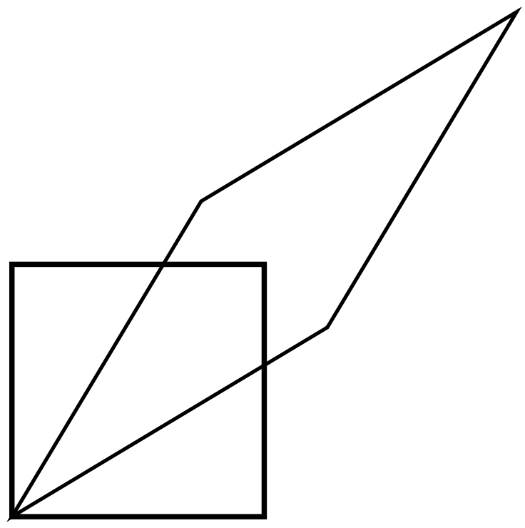
1. The figure illustrates a Lorentz transformation using the conventions employed in section 23.1. For simplicity, the transformation chosen is one that lengthens one diagonal by a factor of 2. Since Lorentz transformations preserve area, the other diagonal is shortened by a factor of 2. Let the original frame of reference, depicted with the square, be A, and the new one B. (a) By measuring with a ruler on the figure, show that the velocity of frame B relative to frame A is . (b) Print out a copy of the page. With a ruler, draw a third parallelogram that represents a second successive Lorentz transformation, one that lengthens the long diagonal by another factor of 2. Call this third frame C. Use measurements with a ruler to determine frame C's velocity relative to frame A. Does it equal double the velocity found in part a? Explain why it should be expected to turn out the way it does.
2. (a) In this chapter we've represented Lorentz transformations as distortions of a square into various parallelograms, with the degree of distortion depending on the velocity of one frame of reference relative to another. Suppose that one frame of reference was moving at relative to another. Discuss what would happen in terms of distortion of a square, and show that this is impossible by using an argument similar to the one used to rule out transformations like the one in figure h on page 656.
(b) Resolve the following paradox. Two pen-pointer lasers are placed side by side and aimed in parallel directions. Their beams both travel at relative to the hardware, but each beam has a velocity of zero relative to the neighboring beam. But the speed of light can't be zero; it's supposed to be the same in all frames of reference.
3. Consider two solenoids, one of which is smaller so that it can be put inside the other. Assume they are long enough so that each one only contributes significantly to the field inside itself, and the interior fields are nearly uniform. Consider the configuration where the small one is inside the big one with their currents circulating in the same direction, and a second configuration in which the currents circulate in opposite directions. Compare the energies of these configurations with the energy when the solenoids are far apart. Based on this reasoning, which configuration is stable, and in which configuration will the little solenoid tend to get twisted around or spit out? [Hint: A stable system has low energy; energy would have to be added to change its configuration.]
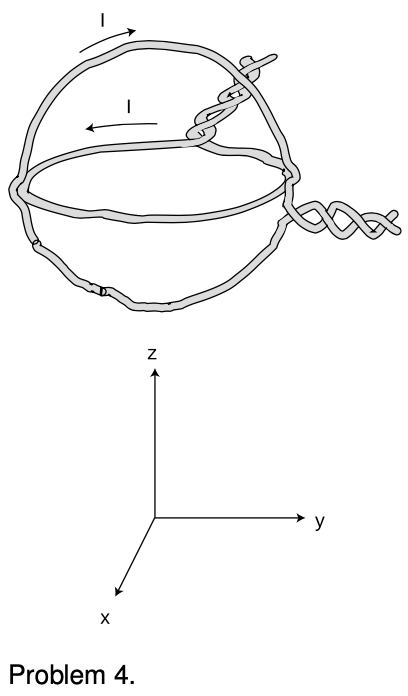 4. The figure shows a nested pair of circular wire loops used to create magnetic fields. (The twisting of the leads is a practical trick for reducing the magnetic fields they contribute, so the fields are very nearly what we would expect for an ideal circular current loop.) The coordinate system below is to make it easier to discuss directions in space. One loop is in the plane, the other in the plane. Each of the loops has a radius of cm, and carries A in the direction indicated by the arrow.
(a) Using the equation in optional section 24.2, calculate the magnetic field that would be produced by one such loop, at its center.
(b) Describe the direction of the magnetic field that would be produced, at its center, by the loop in the plane alone.
(c) Do the same for the other loop.
(d) Calculate the magnitude of the magnetic field produced by the two loops in combination, at their common center. Describe its direction.
5. One model of the hydrogen atom has the electron circling around the proton at a speed of m/s, in an orbit with a radius of 0.05 nm. (Although the electron and proton really orbit around their common center of mass, the center of mass is very close to the proton, since it is 2000 times more massive. For this problem, assume the proton is stationary.) In homework problem 19 on page 604, you calculated the electric current created.
(a) Now estimate the magnetic field created at the center of the atom by the electron. We are treating the circling electron as a current loop, even though it's only a single particle.
(b) Does the proton experience a nonzero force from the electron's magnetic field? Explain.
(c) Does the electron experience a magnetic field from the proton? Explain.
(d) Does the electron experience a magnetic field created by its own current? Explain.
(e) Is there an electric force acting between the proton and electron? If so, calculate it.
(f) Is there a gravitational force acting between the proton and electron? If so, calculate it.
(g) An inward force is required to keep the electron in its orbit -- otherwise it would obey Newton's first law and go straight, leaving the atom. Based on your answers to the previous parts, which force or forces (electric, magnetic and gravitational) contributes significantly to this inward force?
[Based on a problem by Arnold Arons.]
6. Suppose a charged particle is moving through a region of space in which there is an electric field perpendicular to its velocity vector, and also a magnetic field perpendicular to both the particle's velocity vector and the electric field. Show that there will be one particular velocity at which the particle can be moving that results in a total force of zero on it; this requires that you analyze both the magnitudes and the directions of the forces compared to one another. Relate this velocity to the magnitudes of the electric and magnetic fields. (Such an arrangement, called a velocity filter, is one way of determining the speed of an unknown particle.)
7. If you put four times more current through a solenoid, how many times more energy is stored in its magnetic field?
8. Suppose we are given a permanent magnet with a complicated, asymmetric shape. Describe how a series of measurements with a magnetic compass could be used to determine the strength and direction of its magnetic field at some point of interest. Assume that you are only able to see the direction to which the compass needle settles; you cannot measure the torque acting on it.
9. Consider two solenoids, one of which is smaller so that it can be put inside the other. Assume they are long enough to act like ideal solenoids, so that each one only contributes significantly to the field inside itself, and the interior fields are nearly uniform. Consider the configuration where the small one is partly inside and partly hanging out of the big one, with their currents circulating in the same direction. Their axes are constrained to coincide.
(a) Find the magnetic potential energy as a function of the length of the part of the small solenoid that is inside the big one. (Your equation will include other relevant variables describing the two solenoids.)
(b) Based on your answer to part (a), find the force acting between the solenoids.

10. Four long wires are arranged, as shown, so that their cross-section forms a square, with connections at the ends so that current flows through all four before exiting. Note that the current is to the right in the two back wires, but to the left in the front wires. If the dimensions of the cross-sectional square (height and front-to-back) are , find the magnetic field (magnitude and direction) along the long central axis.
11. (solution in the pdf version of the book) The purpose of this problem is to find the force experienced by a straight, current-carrying wire running perpendicular to a uniform magnetic field. (a) Let be the cross-sectional area of the wire, the number of free charged particles per unit volume, the charge per particle, and the average velocity of the particles. Show that the current is . (b) Show that the magnetic force per unit length is . (c) Combining these results, show that the force on the wire per unit length is equal to .
12. (solution in the pdf version of the book) Suppose two long, parallel wires are carrying current and . The currents may be either in the same direction or in opposite directions. (a) Using the information from section 24.2, determine under what conditions the force is attractive, and under what conditions it is repulsive. Note that, because of the difficulties explored in problem 14, it's possible to get yourself tied up in knots if you use the energy approach of section 22.4. (b) Starting from the result of problem 11, calculate the force per unit length.
13. Section 24.2 states the following rule:
For a positively charged particle, the direction of the vector is the one such that if you sight along it, the vector is clockwise from the vector.
Make a three-dimensional model of the three vectors using pencils or rolled-up pieces of paper to represent the vectors assembled with their tails together. Now write down every possible way in which the rule could be rewritten by scrambling up the three symbols , , and . Referring to your model, which are correct and which are incorrect?
14. Prove that any two planar current loops with the same value of will experience the same torque in a magnetic field, regardless of their shapes. In other words, the dipole moment of a current loop can be defined as , regardless of whether its shape is a square.
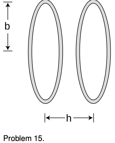 15. A Helmholtz coil is defined as a pair of identical circular coils separated by a distance, , equal to their radius, . (Each coil may have more than one turn of wire.) Current circulates in the same direction in each coil, so the fields tend to reinforce each other in the interior region. This configuration has the advantage of being fairly open, so that other apparatus can be easily placed inside and subjected to the field while remaining visible from the outside. The choice of results in the most uniform possible field near the center. (a) Find the percentage drop in the field at the center of one coil, compared to the full strength at the center of the whole apparatus. (b) What value of (not equal to ) would make this percentage difference equal to zero?
16. (solution in the pdf version of the book) (a) In the photo of the vacuum tube apparatus in figure 24.2.2 on p. 681, infer the direction of the magnetic field from the motion of the electron beam. (b) Based on your answer to a, find the direction of the currents in the coils. (c) What direction are the electrons in the coils going? (d) Are the currents in the coils repelling or attracting the currents consisting of the beam inside the tube? Compare with figure ad on p. 670.
17. In the photo of the vacuum tube apparatus in section 24.2, an approximately uniform magnetic field caused circular motion. Is there any other possibility besides a circle? What can happen in general?
18. This problem is now problem 16 on p. 647
19. (solution in the pdf version of the book) In section 24.2 I gave an equation for the magnetic field in the interior of a solenoid, but that equation doesn't give the right answer near the mouths or on the outside. Although in general the computation of the field in these other regions is complicated, it is possible to find a precise, simple result for the field at the center of one of the mouths, using only symmetry and vector addition. What is it?
20. Prove that in an electromagnetic plane wave, half the energy is in the electric field and half in the magnetic field.
21. (solution in the pdf version of the book) As promised in section 24.7, this problem will lead you through the steps of finding an equation for the combination of velocities in relativity, generalizing the numerical result found in problem 1. Suppose that A moves relative to B at velocity , and B relative to C at . We want to find A's velocity relative to C, in terms of and . Suppose that A emits light with a certain frequency. This will be observed by B with a Doppler shift . C detects a further shift of relative to B. We therefore expect the Doppler shifts to multiply, , and this provides an implicit rule for determining if and are known. (a) Using the expression for given in section 24.7.1, write down an equation relating , , and . (b) Solve for in terms of and . (c) Show that your answer to part b satisfies the correspondence principle.
 22. On p. 697, we defined a quantity , which is often referred to as the spacetime interval. Let's notate it as (cursive letter “I”). The only reason this quantity is interesting is that it stays the same in all frames of reference, but to define it, we first had to pick a frame of reference in order to define an plane, and then turn around and prove that it didn't matter what frame had been chosen. It might thus be nicer simply to define it as the square of the gliding-clock time, in the case where B can be reached from A. Since this definition never refers to any coordinates or frame of reference, we know automatically that it is frame-independent. In this case where , we say that the relationship between A and B is timelike; there is enough time for cause and effect to propagate between A and B. An interval is called spacelike.
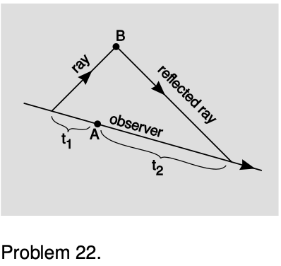
In the spacelike case, we can define using rulers, as on p. 698, but it's awkward to have to introduce an entirely new measuring instrument in order to complete the definition. Geroch suggests a cute alternative in which this case as well can be treated using clocks. Let observer O move inertially (i.e., without accelerating), and let her initial position and state of motion be chosen such that she will be present at event A. Before A, she emits a ray of light, choosing to emit it at the correct time and in the correct direction so that it will reach B. At B, we arrange to have the ray reflected so that O can receive the reflection at some later time. Let be the time elapsed on O's clock from emission of the first ray until event A, and let be the time from A until she receives the second ray. The goal of this problem is to show that if we define as , we obtain the same result as with the previous definition. Since are are simply clock readings, not coordinates defined in an arbitrary frame of reference, this definition is automatically frame-independent.
(a) Show that , as originally defined on p. 697, has the same units as the expression .
(b) Pick an event in the plane, and sketch the regions that are timelike and spacelike in relation to it.
(c) The special case of is called a lightlike interval. Such events lie on a cone in the diagram drawn in part b, and this cone is called the light cone. Verify that the two definitions of agree on the light cone.
(d) Prove that the two definitions agree on in the spacelike case. (e) What goes wrong if O doesn't move inertially?
23. Can a field that is purely electrical in one frame of reference be purely magnetic in some other frame? Use figure e on p. 677.
Exercise 24A: Polarization
Apparatus:
- calcite (Iceland spar) crystal
- polaroid film
1. Lay the crystal on a piece of paper that has print on it. You will observe a double image. See what happens if you rotate the crystal.
Evidently the crystal does something to the light that passes through it on the way from the page to your eye. One beam of light enters the crystal from underneath, but two emerge from the top; by conservation of energy the energy of the original beam must be shared between them. Consider the following three possible interpretations of what you have observed:
(a) The two new beams differ from each other, and from the original beam, only in energy. Their other properties are the same.
(b) The crystal adds to the light some mysterious new property (not energy), which comes in two flavors, X and Y. Ordinary light doesn't have any of either. One beam that emerges from the crystal has some X added to it, and the other beam has Y.
(c) There is some mysterious new property that is possessed by all light. It comes in two flavors, X and Y, and most ordinary light sources make an equal mixture of type X and type Y light. The original beam is an even mixture of both types, and this mixture is then split up by the crystal into the two purified forms.
In parts 2 and 3 you'll make observations that will allow you to figure out which of these is correct.
2. Now place a polaroid film over the crystal and see what you observe. What happens when you rotate the film in the horizontal plane? Does this observation allow you to rule out any of the three interpretations?
3. Now put the polaroid film under the crystal and try the same thing. Putting together all your observations, which interpretation do you think is correct?
4. Look at an overhead light fixture through the polaroid, and try rotating it. What do you observe? What does this tell you about the light emitted by the lightbulb?
5. Now position yourself with your head under a light fixture and directly over a shiny surface, such as a glossy tabletop. You'll see the lamp's reflection, and the light coming from the lamp to your eye will have undergone a reflection through roughly a 180-degree angle (i.e. it very nearly reversed its direction). Observe this reflection through the polaroid, and try rotating it. Finally, position yourself so that you are seeing glancing reflections, and try the same thing. Summarize what happens to light with properties X and Y when it is reflected. (This is the principle behind polarizing sunglasses.)
Exercise 24:B Events and Spacetime
Bell's spaceship paradox
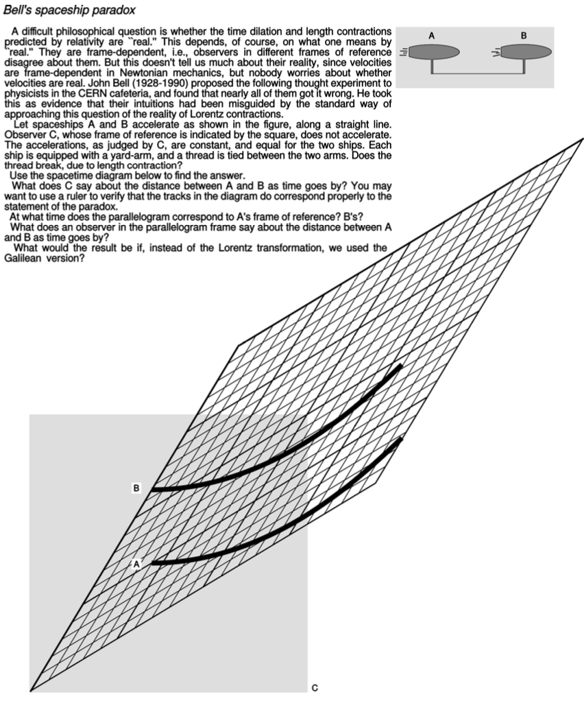
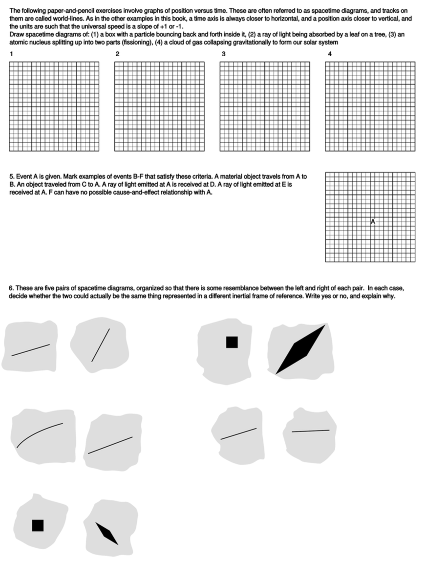
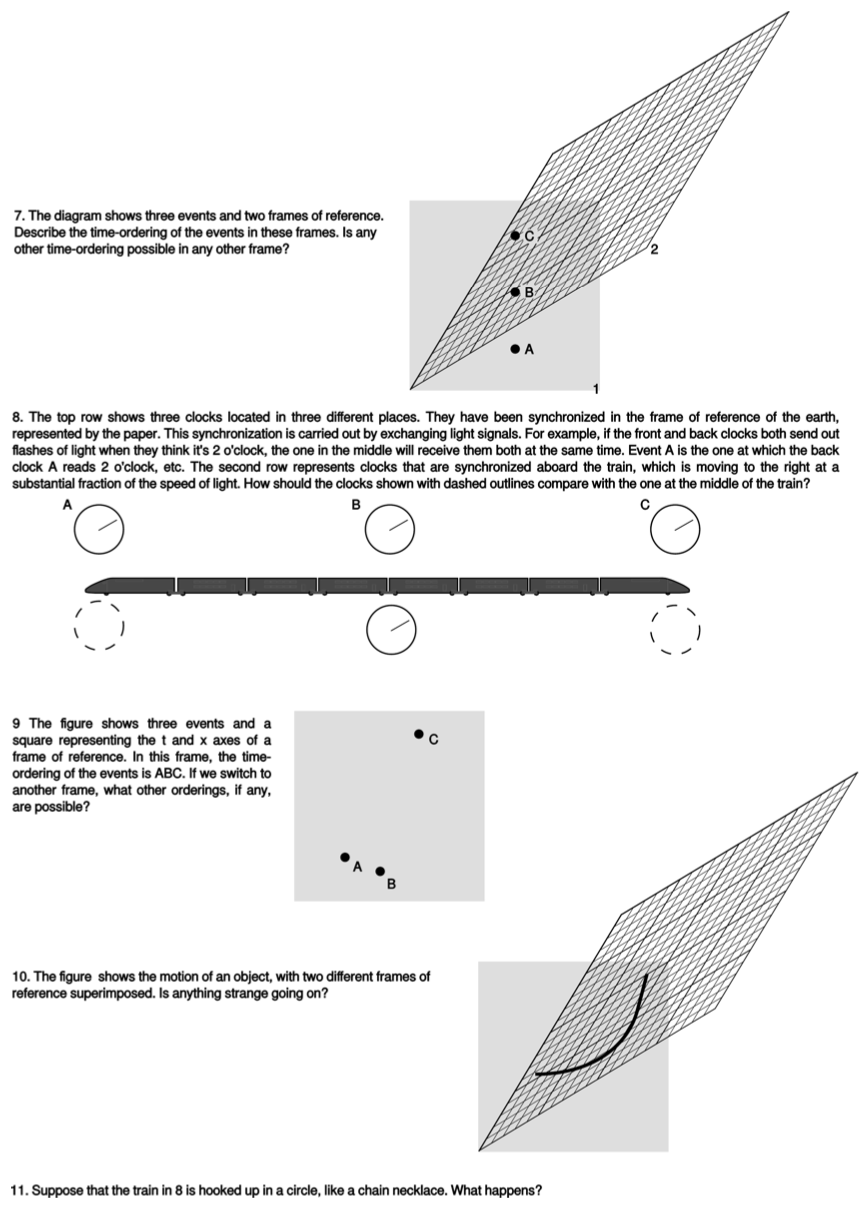
24.8 Summary by Benjamin Crowell, Light and Matter licensed under the Creative Commons Attribution-ShareAlike license.
Calculators and Collections
Equations
- Magnetic dipole moment of a square current loop vCollections Use Equation
- Electric Field for a uniform line of charge vCollections Use Equation
- Magnetic Field (solenoid) vCollections Use Equation
- Magnetic Field (single, circular loop) vCollections Use Equation
- Magnetic Field (long, straight wire) vCollections Use Equation
- Doppler effect for light vCollections Use Equation
- Stored Magnetic Energy (Volume) vCollections Use Equation
- Stored Magnetic Energy vCollections Use Equation
- Stored Electric Energy Density vCollections Use Equation
- Stored Gravitational Energy Density vCollections Use Equation
- Comments
- Attachments
- Stats
No comments |
