LM 25.2 Oscillations Collection
Tags | |
UUID | 1ebc8e6b-f145-11e9-8682-bc764e2038f2 |
25.2 Oscillations by Benjamin Crowell, Light and Matter licensed under the Creative Commons Attribution-ShareAlike license.
25.2 Oscillations
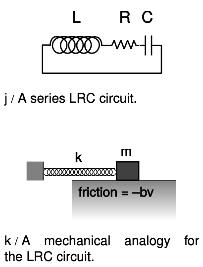
 Figure j shows the simplest possible oscillating circuit. For any useful application it would actually need to include more components. For example, if it was a radio tuner, it would need to be connected to an antenna and an amplifier. Nevertheless, all the essential physics is there.
We can analyze it without any sweat or tears whatsoever, simply by constructing an analogy with a mechanical system. In a mechanical oscillator, k, we have two forms of stored energy,
`K=1/2mv^2`. (2)
In the case of a mechanical oscillator, we have usually assumed a friction force of the form that turns out to give the nicest mathematical results, `F=-bv`. In the circuit, the dissipation of energy into heat occurs via the resistor, with no mechanical force involved, so in order to make the analogy, we need to restate the role of the friction force in terms of energy. The power dissipated by friction equals the mechanical work it does in a time interval `Deltat`, divided by `Deltat`, `P=W"/"Deltat``=FDeltax"/"Deltat``=``Fv=-bv^2`, so
rate of heat dissipation`=-bv^2`. (3)
self-check A:
Equation (1) has `x` squared, and equations (2) and (3) have `v` squared. Because they're squared, the results don't depend on whether these variables are positive or negative. Does this make physical sense? (answer in the back of the PDF version of the book)
In the circuit, the stored forms of energy are
`E_C=1/(2C)q^2` (1')
`E_L=1/2LI^2`, (2')
and the rate of heat dissipation in the resistor is
rate of heat dissipation`=-RI^2`. (3')
Comparing the two sets of equations, we first form analogies between quantities that represent the state of the system at some moment in time:
`xharrq`
`vharrI`
self-check: B
How is `v` related mathematically to `x`? How is `I` connected to `q`? Are the two relationships analogous? (answer in the back of the PDF version of the book)
Next we relate the ones that describe the system's permanent characteristics:
`kharr1"/"C`
`mharrL`
`bharrR`
Since the mechanical system naturally oscillates with a period `T=2pisqrt(m/k)` , we can immediately solve the electrical version by analogy, giving
Rather than period, `T`, and frequency, `f`, it turns out to be more convenient if we work with the quantity `omega=2pif`, which can be interpreted as the number of radians per second. Then
Since the resistance `R` is analogous to `b` in the mechanical case, we find that the `Q` (quality factor, not charge) of the resonance is inversely proportional to `R`, and the width of the resonance is directly proportional to `R`.
Example 4: Tuning a radio receiver
A radio receiver uses this kind of circuit to pick out the desired station. Since the receiver resonates at a particular frequency, stations whose frequencies are far off will not excite any response in the circuit. The value of `R` has to be small enough so that only one station at a time is picked up, but big enough so that the tuner isn't too touchy. The resonant frequency can be tuned by adjusting either `L` or `C`, but variable capacitors are easier to build than variable inductors.
Example 5: A numerical calculation
The phone company sends more than one conversation at a time over the same wire, which is accomplished by shifting each voice signal into different range of frequencies during transmission. The number of signals per wire can be maximized by making each range of frequencies (known as a bandwidth) as small as possible. It turns out that only a relatively narrow range of frequencies is necessary in order to make a human voice intelligible, so the phone company filters out all the extreme highs and lows. (This is why your phone voice sounds different from your normal voice.)
`=>` If the filter consists of an LRC circuit with a broad resonance centered around 1.0 kHz, and the capacitor is `1 muF` (microfarad), what inductance value must be used?
`=>` Solving for `L`, we have
`=1/((10^(-6) F)(2pi×10^3 s^(-1))^2)`
`=2.5×10^(-3) F^(-1)s^2`
Checking that these really are the same units as henries is a little tedious, but it builds character:
`F^(-1)s^2=(C^2"/"J)^(-1)s^2`
`=J*C^(-2)s^2`
`=J"/"A^2`
`=H`
The result is 25 mH (millihenries).
This is actually quite a large inductance value, and would require a big, heavy, expensive coil. In fact, there is a trick for making this kind of circuit small and cheap. There is a kind of silicon chip called an op-amp, which, among other things, can be used to simulate the behavior of an inductor. The main limitation of the op-amp is that it is restricted to low-power applications.
25.2 Oscillations by Benjamin Crowell, Light and Matter licensed under the Creative Commons Attribution-ShareAlike license.
Calculators and Collections
Equations
- Energy in a Spring vCollections Use Equation
- Kinetic Energy KurtHeckman Use Equation
- Friction Force vCollections Use Equation
- Power dissipated by friction vCollections Use Equation
- Power dissipated by friction using force vCollections Use Equation
- Spring Oscillation Period vCollections Use Equation
- Oscillation Period `(LC)` vCollections Use Equation
- `L=1/(Comega^2)` vCollections Use Equation
- Angular Frequency vCollections Use Equation
- Angular Frequency of Oscillating Spring vCollections Use Equation
- Rate of heat dissipation in resistor vCollections Use Equation
- Inductor's Energy (2') vCollections Use Equation
- Energy of a Capacitor vCollections Use Equation
Collections
- Comments
- Attachments
- Stats
No comments |
