The Pulleys Belts Gears and Levers Calculator includes formulas for Levers, Belts, Pulleys and Gears calculator  Lever and Fulcrumcontains equations related to speeds, diameters and RPMs in systems of belts, pulleys and gears. The equations include the following:
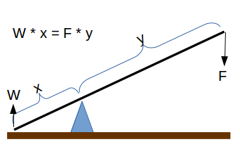
- Lever Beam Length: Computes the length of a lever (beam) on one side of a fulcrum needed to lift an object based on the objects weight and the length of the beam on the other side of the fulcrum.
- Leverage Lift Weight: Computes the weight that can be lifted using a lever based on the downward force and the length of the lever on either side of the fulcrum.
- Fulcrum Position (x): Computes the position of the fulcrum needed in a lever to lift a weight (W) with a downward force (F) with a beam of length (L), where L = x + y.
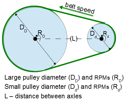
- Belt Length: Computes the length of a belt that goes around two pulleys of different diameters separated by a specific distance.
 two pulley system
 - Belt Speed: Computes the speed a belt travels based on the diameter of the pulley and the RPMs.
- Pulley RPMs: Computes the RPMs of a pulley based on the speed of the belt and the diameter of the pulley.
- 2nd Pulley RPMs: Computes the RPMs of a second pulley in a two pulley system when the RPM and Diameter are known for one pulley and the diameter of the second pulley is also known.
- 2nd Pulley Diameter:- Computes the diameter of a second pulley in a two pulley system based on diameter and RPM of one pulley and the RPMs of the second.
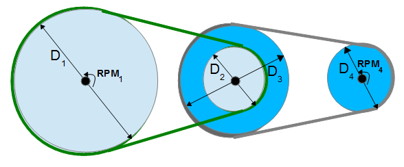
- RPM of 4th pulley on three shafts: Computes the RPMs of a fourth pulley on a three shaft system when the RMPs of the first shaft is known and the four diameters.
- 2nd Gear RPM: Computes the RPMs of a second gear when the RPM and number of teeth are known for the first gear, and the number of teeth are known for the second gear.
Belt and Pulley Systems
A belt and pulley system is characterized by two or more pulleys in common to a belt. This allows for mechanical power, torque, and speed to be transmitted across axles. If the pulleys are of differing diameters, a mechanical advantage is realized.  pulley transfer
A belt drive is analogous to that of a chain drive, however a belt sheave may be smooth (devoid of discrete interlocking members as would be found on a chain sprocket, spur gear, or timing belt) so that the mechanical advantage is approximately given by the ratio of the pitch diameter of the sheaves only, not fixed exactly by the ratio of teeth as with gears and sprockets.
In the case of a drum-style pulley, without a groove or flanges, the pulley often is slightly convex to keep the flat belt centered. It is sometimes referred to as a crowned pulley. Though once widely used on factory line shafts, this type of pulley is still found driving the rotating brush in upright vacuum cleaners, in belt sanders and bandsaws. Agricultural tractors built up to the early 1950s generally had a belt pulley for a flat belt (which is what Belt Pulley magazine was named after). It has been replaced by other mechanisms with more flexibility in methods of use, such as power take-off and hydraulics.
Just as the diameters of gears (and, correspondingly, their number of teeth) determine a gear ratio and thus the speed increases or reductions and the mechanical advantage that they can deliver, the diameters of pulleys determine those same factors. Cone pulleys and step pulleys (which operate on the same principle, although the names tend to be applied to flat belt versions and V belt versions, respectively) are a way to provide multiple drive ratios in a belt-and-pulley system that can be shifted as needed, just as a transmission provides this function with a gear train that can be shifted. V belt step pulleys are the most common way that drill presses deliver a range of spindle speeds.
Gears
Systems of gears work in a similar fashion to pulleys and belts,  two gear system except there is no belt and the gears are inter-meshed with the teeth of one gear turning the teeth of a second gear. In this case, the RPM are a function of the number of teeth on the gear. The relationship between the gears is expressed as follows:
`RPM_1 * Teeth_1 = RMP_2 * Teeth_2`
Where:
- RPM1 is the revolutions per minute of the first gear
- Teeth1 is the number of teeth in first gear
- RMP2 is the revolutions per minute of the second gear
- Teeth2 is the number of teeth in the second gear.
The assumption is compatible teeth in the two gears.
See Also
- Pendulum - Calculator with equations related to a pendulum.
- Engine - Calculator with equations related to combustion engines.
Simple Machine Calculators
- Lever Beam Length
- Leverage Lift Weight
- Fulcrum Position
- Belt Length
- Belt Speed
- RPMs to Linear Velocity
- RPMs from linear velocity and diameter
- 2nd Pulley RPMs
- 2nd Pulley Diameter
- RPM of 4th pulley on three shafts
- 2nd Gear RPM
- Sum of Two Lengths
References
- Wikipedia - http://en.wikipedia.org/wiki/Pulley
- Handyman In Your Pocket (2012 Richard A. Young and Thomas J. Glover) Sequoia Publishing of Littleton, CO.